1. Composition and structure of filter and parallel capacitors device
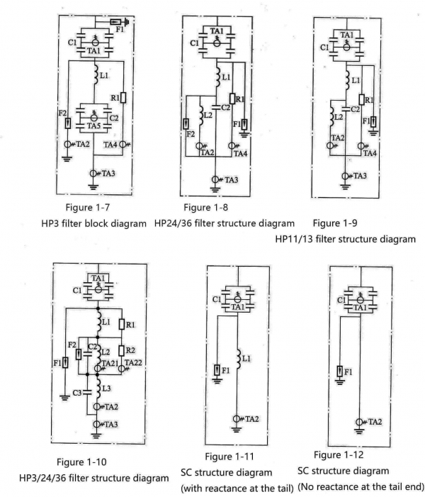
🍏The AC filter consists of high and low voltage capacitor banks (capacitor towers), reactors, resistors, lightning arresters, current transformers (oil-filled, silicone rubber, photocurrent transformers) and other metal connectors, supports, protective parts, etc. composition. The AC filters often used in the design of DC converter stations include HP3 filter (single-tuned filter, the structure is shown in Figure 1-7), HP24/36 filter (double-tuned filter, the structure is shown in Figure 1-8). shown), HP11/13 filter (double-tuned filter, structure shown in Figure 1-9) and HP3/24/36 filter (three-tuned filter, structure shown in Figure 1-10).Parallel capacitors are composed of high-voltage capacitor banks (capacitor towers), reactors, current transformers (oil-filled, silicone rubber, photocurrent transformers) and other metal connectors, supports, and guards. There are two types of parallel capacitors used in DC converter stations: capacitors with current-limiting reactors at the tail (structure shown in Figure 1-11) and capacitors without current-limiting reactors at the tail (structure shown in Figure 1-12).
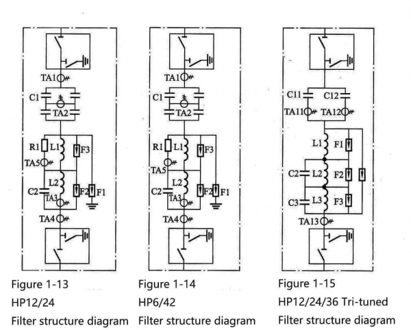
🍎The components of the DC filter and the AC filter are the same, and they are also composed of high and low voltage capacitor banks. It is composed of circuit breakers, arresters, current transformers (oil-filled, silicone rubber, photocurrent transformers) and other metal connectors, supports, and guards. In addition, some of the DC projects currently in operation in China use indoor DC fields (such as the Hami converter station under construction at Yinchuan East Converter Station, which was put into operation in February 2011), and the indoor DC fields also need DC through walls. Casing equipment. Commonly used DC filters include HP12/24 filter (double tuning, structure shown in Figure 1-13), HP6/42 filter (structure shown in Figure 1-14), HP12/24/36 filter ( Three tuning, the structure is shown in Figure 1-15), etc.
2. Power capacitors
Power capacitors and other components together form AC and DC filter circuits to filter harmonic currents and provide reactive power. In the whole investment of AC-DC filter and parallel capacitors device, the investment of power capacitor accounts for most of the investment, and the design and manufacture of high-voltage capacitors used in DC converter stations have high technical requirements and complex processes, and their quality and performance are directly related. Affecting the safe and stable operation of these devices, the high-voltage capacitor tower of the filter and parallel capacitor device is shown in Figure 1-16.
1. Capacitor structure
🍐There are many types of capacitors. As shown in Figure 1-17 and Figure 1-18, the structure diagram and physical map of the most widely used metal-shell type power capacitor in DC converter stations are shown. Wire, discharge resistor, etc.), shell and outlet structure are composed of 3 parts, the core or the body composed of multiple cores is assembled with the shell and the outlet structure, and the capacitor is made by vacuum drying, impregnation treatment and sealing. It adopts a metal rectangular shell, and the core is composed of internal components (small capacitors) and insulating parts of the capacitor that are wound and pressed into a flat shape. The high-voltage capacitor cores (small capacitor components) are connected in series and parallel, and the outgoing wires are insulated with porcelain sleeves. Figure 1-19 is a schematic diagram of the internal structure of the corresponding power capacitor. The structure of each component is introduced below.
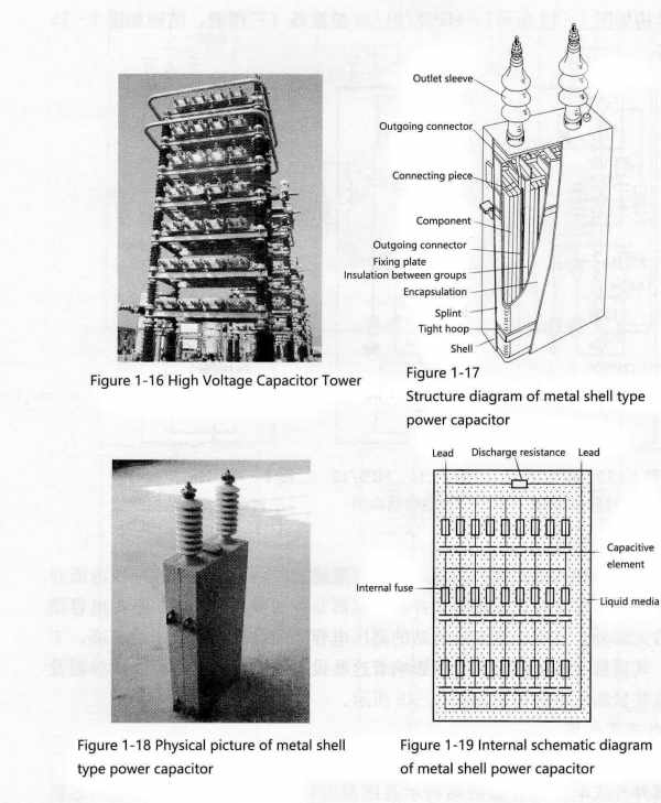
(1) Shell. In addition to accommodating the main components of the capacitor, a core group and insulating oil, it is also conducive to heat dissipation and is equipped with hanging climbs and/or feet that meet the requirements of handling and installation. It is made of thin steel plate (generally 1~2mm in thickness) to meet the compensation of the volume change of insulating oil with the change of internal temperature, especially to ensure that no negative pressure occurs inside the capacitor and to ensure that the internal insulation performance is not reduced.
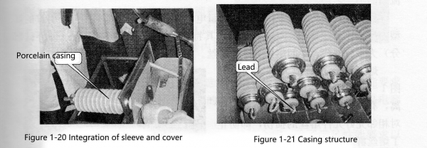
🍊(2) Outlet structure. It consists of a porcelain bushing, an outlet wire and an insulating tube sleeved outside the outlet wire. Porcelain sleeve is the external insulation between the capacitor outlet and the outer casing. Its height and the number of sheds are determined by the insulation level, that is, the voltage level. Its parameter index is the creepage distance (referred to as the creepage distance). At the same time, the porcelain sleeve wall also undertakes the insulation (internal insulation) between the outgoing wire and the shell together with the insulating tube and the insulating oil in the gap. The outgoing wires are copper stranded wires or copper rods, and the insulating tube is a paper tube wound with cable paper. Figure 1-20 shows the physical picture of the integration of the casing and the cover, and Figure 1-21 is the structural diagram of the casing.
(3) Core group. This part is the core part of the capacitor. It is mainly composed of several components, internal fuses (configured when necessary), connecting sheets, insulating parts, encapsulation parts and fasteners after being pressed and connected according to the specified series and parallel connection methods.
🍋1) Element: It is made of a certain thickness and number of layers of dielectric (capacitor paper or capacitor paper and polypropylene film or polypropylene film) and a polar plate (usually aluminum foil) if it is rolled for a certain number of turns and then flattened. When the width of the aluminum foil is smaller than the width of the medium, the electrodes are drawn out by the leads and become a hidden foil type (commonly used in full-paper dielectric and composite dielectric capacitors); when the width of the aluminum foil is greater than or equal to the medium, the aluminum foil protrudes out, and the components are connected by connecting wires. , connected in parallel, called protruding foil type (commonly used in all-film dielectric capacitors).
The components are usually connected in parallel first and then in series. If there is an internal fuse, the internal fuse and the components are regarded as one and then connected in parallel first and then in series.
🍌2) The inner fuse is used as the inner protection of the capacitor.
From the perspective of fuse, capacitors are divided into inner fuse, outer fuse and non-fuse capacitors, among which inner fuse capacitors are more used in converter stations. The inner fuse is the most basic protection device for capacitor components. It is connected in series with the components, usually galvanized pure copper wire. A small part of the capacitor does not affect the operation of the entire capacitor. However, due to the development of the capacitor itself (such as the increase of the electric field strength, the increase of the component capacity), the internal fuse cannot be set for the small-capacity capacitor.
🍉Metal shell capacitors used as AC and DC filters and parallel capacitors in HVDC converter stations should have dual functions of reactive power compensation and filter. As we know, the external fuse and non-fuse capacitors have such defects: after the component failure, the capacitance value and voltage distribution of the capacitor unit and capacitor bank will change greatly, so the component failure will make the AC filter filter performance due to the capacitance value. The change of the voltage distribution is larger and worse, and the larger change of the voltage distribution will cause the voltage stress of other capacitor units to increase. In addition, due to the limited breaking capacity of the external fuse, the capacitor capacity of the external fuse is much smaller than that of the internal fuse, which means that the entire set of filters increases the cost due to the large number of capacitor units. Therefore, the internal fuse capacitor is also the best choice for high claw voltage DC converter station.
At present, the domestic large-capacity capacitors used in the DC converter station have basically all adopted the new internal fuse technology introduced from abroad, that is, the “separated” structure, which is characterized by the fact that the connecting part (ie the exposed part) at both ends of the fuse is multi-strand parallel winding , the middle melt is a single-strand fuse.
🍇The fuses are placed between stacked components (as shown in Figure 1-22), and each fuse is completely separated, which effectively prevents damage to the fuses of the adjacent intact components when the fuses act, that is, prevents the fuses from being damaged. The occurrence of mass explosion also prevents the contamination of insulating oil caused by the action of the fuse.
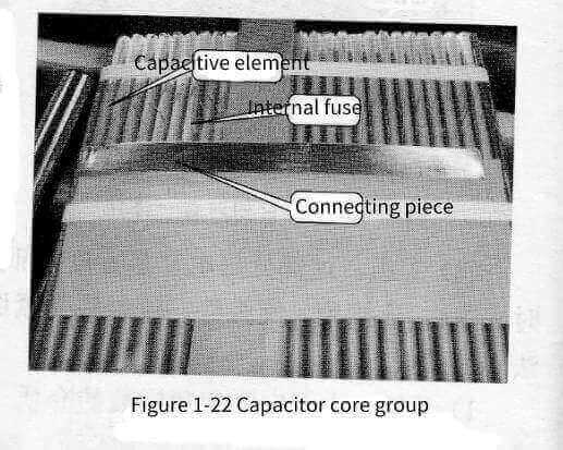
The performance of the internal fuse protection of the capacitor determines the success and inspection of the action when the capacitor unit fails, which is directly related to the size of the unbalanced current of the AC and DC filters and parallel capacitors.
🍓3) Connecting sheet: usually galvanized pure copper sheet, used for medium and parallel connection of components, that is, the electrical connection inside the capacitor.
4) Insulators: usually cable paper and electrical cardboard, as insulation between component groups (components connected in parallel are a component group).
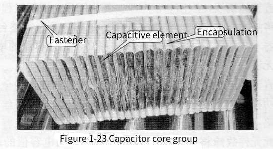
🍈5) Encapsulation: Usually made of cable paper, it wraps the connected components as a whole, as the insulation of the live part of the capacitor to the shell, as shown in Figure 1-23.
6) Fastener: its function is to fasten the package. In the manufacturing stage of all-paper capacitors and composite dielectric capacitors, steel tapes are used to fasten (wrap), and plastic tapes are used in the manufacture of all-film capacitors, as shown in the figure 1-23.
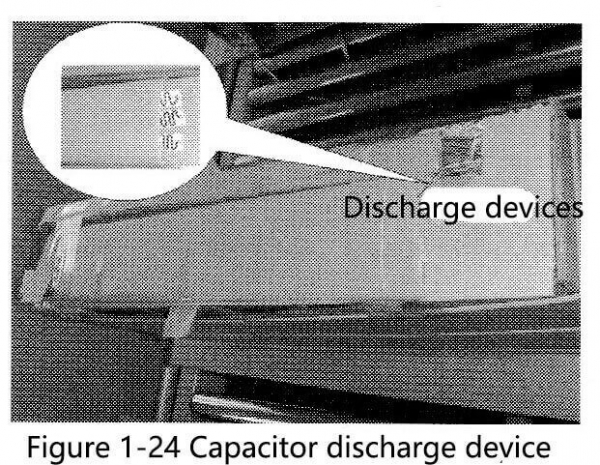
🍒7) Discharge device: Its function is that when the capacitor is out of operation, the discharge device discharges the stored charge in the capacitor to ensure the safety of people who contact the parallel capacitors and the safety of the capacitor being put into operation again. At present, glass glaze resistors are commonly used, and there are two types: sheet and cylindrical. Recently, sheet resistors are mostly used. Capacitors used in DC converter stations are generally designed with discharge devices, which are connected between the two outlet wires inside the capacitor. The discharge devices are shown in Figure 1-24.
(4) The medium of the capacitor. The selection of capacitor dielectric is selected by the designer according to the user’s electrical performance requirements. It mainly determines the electrical performance of the capacitor, but the manufacturing process is also an important link for the capacitor to meet the performance requirements.
🍑In the design process of capacitors, how to choose the insulating medium reasonably should not only meet the performance requirements, but also consider the manufacturing economy. Therefore, under the premise of satisfying the electrical performance, it is always hoped that the capacitor should be small in size and light in weight (both of which determine the economy), withstand working voltage (determine the life of the capacitor) and short-term impulse voltage (determine the reliability of work). ) has strong capability and low loss. But the relationship between them is always contradictory. Usually, the capacitor with high dielectric constant will be small in size and light in weight, but the medium with high dielectric constant will also have large loss; medium with small polarity usually has small loss, However, the withstand voltage performance is also poor; on the contrary, the dielectric loss with large polarity is large, but its ability to withstand voltage is also strong. Therefore, it should be comprehensively considered and measured in the design. The insulating medium inside the capacitor includes solid medium and liquid medium.
1) Solid medium. The solid dielectrics of oil-immersed capacitors are capacitor paper and polypropylene film. The former is the only choice in the manufacture of full-paper and composite dielectric capacitors. The designer can only choose the thickness and width of the container paper, and there is no room for it. With the development of capacitor manufacturing technology, all-film capacitors now occupy an absolute dominant position, and the performance of capacitor paper is no longer introduced in this book.
🥭Polypropylene film is almost the only solid material currently used to manufacture oil-immersed high-voltage shunt power capacitors and oil-immersed high-voltage filter capacitors. In the period when composite dielectric capacitors were mainly produced, to solve the permeability of capacitor cores, single-sided or double-sided mechanical films were used to ensure that insulating oil was not penetrated between the mold and the aluminum foil. Now in the manufacture of all-film capacitors, double-sided roughened films have been all used.
Polypropylene film, as the name implies, its raw material is polypropylene. According to the different production processes, there are two kinds of flat film and tubular film. Sliced and sliced. The polypropylene film used in the manufacture of capacitors is about 95% crystalline, while the ordinary polypropylene film is basically amorphous, so the polypropylene film for capacitors has high electrical properties and heat resistance. In order to improve the permeability, the surface of the film was roughened.
🍍2) Liquid medium. With the development of science, the liquid medium of high-voltage oil-immersed metal shell capacitors has been continuously developed and introduced new varieties, and the old ones have been eliminated. The comprehensive indicators of its physical, chemical and electrical properties have been continuously improved, which has continuously improved the performance of high-voltage oil-immersed capacitors.
The earliest used capacitor oil is not artificially synthesized, but extracted from mineral oil by rectification. Its electrical properties are slightly better than that of transformer oil. This is a saturated alkane with a straight-chain structure. Daqing and Karamay, Daqing products are pure saturated alkanes, Karamay products have some naphthenic structures, and the performance is slightly better. Since the capacitor oil is not inspiratory, it is not conducive to solving the problem of partial discharge, and other performance indicators are not as good as synthetic materials, which have been eliminated by the capacitor industry at present. Its similar products are still widely used in the transformer industry and the cable industry (transformer oil and cable oil).
🥝My country used chlorinated biphenyls (PCBs) in the 1960s, which is a mixture of pentachlorinated biphenyls and trichlorinated extracts, but because of its high toxicity, it has also been banned worldwide.
At present, the liquid media still in use are as follows:
🍅(a) Alkylbenzene (AB). It is mainly dodecylbenzene (DDB). Dodecylbenzene has two types: soft and hard. Hard DDB has methyl groups on the alkane chain, while soft DDB has no methyl groups on the alkyl chain. Most of them are produced in my country. Soft DDB. The straight-chain DDB is slightly inferior to the branched-chain DDB in terms of air intake.
The chemical structural formula of rigid DDB (15-20 carbons) is shown in Figure 1-25. The chemical structure of soft DDB is shown in Figure 1-26.

🍆(b) Diarylethane (PXE). Diarylethane is phenylxylylethane, the scientific name is 1-yl-1-dimethylethane (the Japanese trade name is SAS-296, referred to as S oil), this structure has three kinds of allotropes body, namely ortho-1-phenyl-1-dimethylethane, meta-1-phenyl-1-dimethylethane: ethane and para-1-phenyl-1-dimethylethane . The mixture of three allotropes is used in production in my country. The proportions of the three components vary from manufacturer to manufacturer, but they have little effect on their performance. The chemical structure is shown in Figure 1-27.

(c) Phenylethylphenylethane (PEPE). Known as low temperature S oil in China, this structure also has ortho, meta and para isomers, and its chemical structure is shown in Figure 1-28.

🥑(d) Isopropyl Biphenyl (IPB). Isopropyl biphenyl has various isomers, and its chemical structure is shown in Figure 1-29.

(e) Benzyltoluene (M/DBT). Benzyltoluene is a mixture of monobenzyltoluene and bisbenzyltoluene. The domestic abbreviation is benzyl toluene, and sometimes the French appellation -C101 is used. The group in which a hydrogen atom on the methyl group is removed from toluene is called a methyl group or a benzyl group, that is, C, H, CH, one. The mixing ratio of monobenzyltoluene and bisbenzyltoluene is 75:25, and its chemical structure is shown in Figure 1-30.

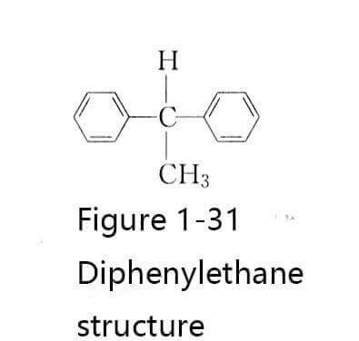
🥦(f) SAS-40. SAS-40 is a blend of monobenzyltoluene and diphenylethane. It was first manufactured in Japan. The chemical structure of diphenylethane in its composition is shown in Figure 1-31.
2. Parameters and design of capacitor components
(1) The thickness of the dielectric between the electrodes. When choosing the thickness of the dielectric between the electrodes, both a sufficiently high breakdown field strength and the highest possible partial discharge field strength should be considered. Within a certain range, the breakdown field strength increases with the increase of the dielectric thickness, and reaches the maximum when the thickness is 70~90pm; the partial discharge field strength decreases with the increase of the dielectric thickness. High-voltage capacitors generally choose a dielectric thickness of 60~80pm.
🥬(2) Component compression coefficient. The ratio of the nominal thickness of the medium between the element plates to the actual thickness after compression is called the compression coefficient K. The component compression factor also has a certain influence on the electrical performance of the capacitor. Under the action of high-voltage AC voltage, when the component compression coefficient increases, its dielectric coefficient and breakdown field strength increase, but the dielectric loss tangent value will increase accordingly. The compression factor should not be too large. If it is too large, it will not only make it difficult to press the core, but also easily damage the insulating medium of the component lead sheet, etc., and even cause breakdown.
The selection of the compression coefficient of the current mainstream product full-film power capacitors should be determined in order to facilitate the flow of the infiltrating agent between the interfaces, the selection of the compression coefficient and the outlet method, the structure of the lead sheet, whether the aluminum foil is folded, and the swelling of the film after dipping. circumstances and other factors. The compression coefficient of domestic capacitors is generally about 0.8.
🥒(3) Selection of average working field strength. Reasonable selection of working field strength is the core issue of design, which is usually determined after comprehensive consideration of material performance and quality, production technology level, combined medium rapid aging test data and practical experience. From the point of view of short-term electrical breakdown, thermal breakdown and partial discharge, the selected working field strength value must have sufficient margin to make the inside of the capacitor safe under the action of instantaneous overvoltage or rated working voltage. Stable operation.
Capacitors used in HVDC converter stations are generally metal aluminum foil capacitors, and their performance, technical and economic indicators are characterized by their characteristics (kvar/dm or kg/kvar) and ratings. The average working field strength of the capacitor dielectric plays a decisive role in the technical and economic indicators of the capacitor. The specificity of the capacitor is approximately proportional to the square of the average working field strength of the capacitor; while the volume of the capacitor is inversely proportional to the square of the average working field strength. Taking a higher flat horse working field strength means that the capacitance value of the dielectric material per unit volume is higher, and the volume of the capacitor is smaller; the increase in the capacitance value per unit volume and the reduction in the volume of the capacitor means less material consumption and lower cost. The selection of field strength and dielectric material also determines the operating life of the capacitor. However, whether a higher field strength can be selected depends on the ability of the dielectric to withstand Yangqiang, the starting voltage of partial discharge at the edge of the point electrode, and the ability of the dielectric to withstand overvoltage. , dielectric thickness, margin of electrode edge, electrode type, etc. At present, the average working field strength of AC filter capacitors in converter stations is 60~70kV/mm.
🌽(4) Thickness of capacitive element. The thickness of the capacitive element is related to the size of the plate area. When the relevant dimensions such as the width of the plate and the diameter of the winding mandrel are constant, the area of the plate increases and the thickness of the element also increases. If the area of the polar plate is too large, the field strength of the mountain pass will be reduced, and the capacitive element will be thickened, and S-shaped wrinkles will appear after being flattened, which will lead to field strength distortion at this place during operation, resulting in a great increase in the probability of breakdown at this place. If the plate area is too small, to keep the external capacitance constant, the number of components will increase, which will bring trouble to the manufacturing. Considering the above two factors, the thickness of polyendene film capacitor elements is usually between 8~20mm.
(5) Edge width of capacitive element. The size of the edge width of the capacitor element should ensure that the corona and flashover voltage along the edge is higher than the mountain voltage of the dielectric between the poles. The selection of the edge width can be considered according to the dielectric strength of the surface of the solid medium in the oil is 0.5–0.9kV/mm, and the negative tolerance of the capacitor and film width and the positive tolerance of the width of the electrode plate (aluminum box) and the rolling The components may be misaligned and other factors. Generally, the minimum edge width of capacitive components can be 8-10mm.
🥕(6) Core design. The core is the main body of the power capacitor, which is composed of a certain number of components according to the specified connection method to meet the technical requirements of the product. There should be sufficient dielectric strength between the series element groups in the core and the outer shell of the core.
1) The series and parallel connection of capacitive elements, the voltage and capacitance of the capacitive elements are determined by the selected element parameters and the size of the 8. Due to the thickness of the inter-electrode dielectric and the limitation of the plate, they are usually not very large. Therefore, for products with high rated voltage, component application should be adopted, and for products with large nominal capacitance, a core composed of parallel components should be adopted. Capacitors used in DC converter stations are usually of medium-parallel hybrid structure in order to meet the needs of the product withstanding voltage and capacitance at the same time.
🥔2) Internal fuse. If all the capacitive elements inside the capacitor are connected in parallel, connect a fuse to each element for protection. When a component breaks through, other components connected in parallel with it all discharge to the breakdown point, so that the fuse of the breakdown component is blown, the capacitance value of the capacitor changes very little, and the capacitor can still continue to run. However, the fuses of other components should not be blown when discharging to the breakdown point and under the allowable overvoltage and overcurrent
In-capacitor fuses are usually made of tinned copper wire. The diameter of the fuse is generally 0.25~0.35mm, and its length is determined by the combination of calculation and experiment according to the different energy distribution of different products.
🍠3) Selection of insulating parts. Insulators are required to insulate the series capacitive elements, the core (or the body) and the metal shell. These insulating parts should be able to withstand the withstand voltage test of the product with sufficient margin. The insulating parts are mostly made of 0.12rnn thick cable paper or 0.5~-2mm thick electrical cardboard. When the total thickness of oil-immersed cable paper is less than 20 layers, its breakdown field strength is basically unchanged, while the electrical cardboard mountain breakdown field strength decreases with the increase of its thickness.
🥐(7) Shell design. In addition to good sealing and certain mechanical strength, the shell of the capacitor should also have good heat dissipation or sufficient external insulation performance according to different requirements of the product. The rectangular metal casing most commonly used in DC converter stations has a good heat dissipation effect. When the casing volume is constant, as the ratio of the length to the width of the casing increases, the heat dissipation area will gradually increase, but the utilization rate of the steel plate is poor. In addition, the thin metal casing has the effect of compensating for changes in the volume of the sanitizer. The outgoing wire insulation of metal external photo capacitors used in converter stations is basically made of porcelain bushings.
(8) Selection of medium and plate. The dielectric and the plate are important materials for power capacitors, and the dielectric is the key material that determines the performance of the product. Selecting the medium together can make the capacitor have good performance and advanced technical and economic indicators. In order to improve the energy storage factor eE, a combined medium is also used in the container. In the era of film paper, the combined medium was oil-impregnated capacitor paper for capacitors, and now a composite medium composed of synthetic oil and polypropylene film is often used.
🥯When selecting the medium, the technical requirements of the product such as dielectric loss, partial discharge characteristics, and aging performance should also be considered. A common plate material for power capacitors is aluminum foil. Since most capacitors use winding and flattened components, the plates are subject to mechanical force when the components are rolled; heat is generated when the current passes through the plates, and the higher the frequency, the greater the effective resistance of the plates. , the more severe the fever. Therefore, there are certain requirements for the mechanical selection strength, electrical conductivity and thermal conductivity of the polar plate.
The high-voltage shunt capacitor is a high electric field strength device. During the production process, it is processed by high vacuum drying and filled with liquid medium under high vacuum. In order to solve the problem of high oil pressure, low pressure and even negative pressure caused by factors such as temperature and load during storage and use, the deflection of the large surface of the shell is used for metal shell capacitors (although the oil is relatively small) to solve the problem. .
3. Reactor
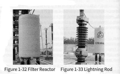
🍞Reactors, capacitors, and resistors together form a filter circuit (reactors and capacitors are generally grouped into a parallel capacitor circuit), which is used to filter harmonic currents. The second purpose of adjusting the reactors in the parallel capacitor bank is to limit the inrush current generated during the switching process. The reactors used in domestic AC filters are all dry-type reactors, as shown in Figure 1-32. Its structure is equivalent to a winding, with no iron core inside, air insulation, and resin reinforced with glass fiber for the outside. insulation. The selection of the filter is determined by the parameters of the two filter banks. In order to protect the reactor from being damaged by overvoltage, the arrester of the corresponding voltage level is generally applied on the branch circuit of the reactor, as shown in Figure 1-33.
4. Resistors
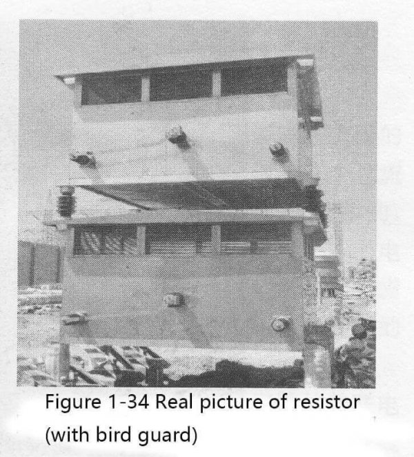
🥖Resistors (as shown in Figure 1-34), filter reactors and capacitors together form a filter circuit to filter out harmonic currents. The physical characteristics of resistors are to convert electrical energy into heat energy, and are energy-consuming components, which play the role of voltage divider, current shunt and heat dissipation in AC and DC filter networks. The damping resistor used in the AC filter is also air-insulated and installed in an air-ventilated box (bird-proof cover). In addition to determining the selection of the resistor according to the parameters of the AC filter, factors such as its thermal capacity and local altitude should also be considered.
5. How to install the equipment
🥨AC and DC filters and shunt capacitor equipment are mainly capacitors, reactors and resistors, of which the number of capacitors is the largest. The installation methods of capacitors are supported and suspended, and reactors and resistors are generally supported. The two installation methods of capacitors have been used in some DC projects, and the support type is more used than the suspension type.
There are two installation methods for the capacitor unit on the bracket: horizontal and vertical. Figure 1-34 The physical diagram of the resistor (with bird-proof cover). The horizontal and vertical installation are shown in Figures 1-35 and 1-36.
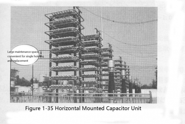
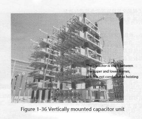
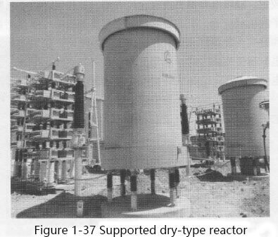
🧀Shorter interlayer post insulators can be used for horizontal installation, and the connecting wires between units are also short, so the replacement of faulty capacitors is more convenient, and the mechanical stress of the main post insulators at the bottom of the capacitor unit can be reduced. Possibility is greater than vertical. The characteristics of vertical installation are the opposite of horizontal installation. In domestic DC converter stations, such as single-group AC filters or capacitors in parallel capacitors are often used, usually vertical double-tower installation is used. In addition, when the support capacitor is installed, the high potential is on the top, and the conductor connected to the busbar is led from the top. The other components of the filter equipment have low potential, small size and mass, and are all supported by support installation, such as the support type dry reactor shown in Figure 1-37.
🍡At present, due to the prominent advantages of DC transmission, the distribution areas of ultra-high voltage converter stations and UHV converter stations that have been put into operation in China are more extensive. With the Northwest Yinchuan Dongshi 660kV converter station put into operation and the double-pole taxi 800kV Hami converter station planned to be put into operation in 2014, the indoor DC filter capacitor tower was also born in the DC filter installation. The high-end capacitor tower of the DC field will be installed indoors, and the essence of the equipment will remain unchanged.

