Working status of electrolytic capacitors – LLC resonant converter is one of the best DC/DC power converters in the past 30 years. It has the advantages of high duty cycle of bridge converter and low voltage and zero current switching. The advantages of switching loss and low EMI have led to more and more applications, ranging from 100-watt switching power supplies to on-board chargers and charging piles for electric vehicles with 10kW or higher power. It can achieve constant voltage/constant current operating mode very well.
1 Working status of electrolytic capacitors-ripple current generated by half-bridge LLC resonant converter
For a single-phase AC input LLC resonant converter, a power factor correction unit needs to be configured. At this time, the ripple current involved in the DC bus capacitor of the LLC resonant converter is the 100Hz ripple current component and switching frequency ripple current component generated by the power factor correction circuit, and the switching frequency ripple current generated by the LLC resonant power converter. Portion.
When the LLC resonant converter has the maximum output power, it draws the largest current from the DC bus, including both DC and AC components. The AC component must be absorbed by the DC bus capacitor connected in parallel to the DC bus. The main waveforms of the half-bridge LLC are shown in Figure 11-1. Channel 2 in the figure is the current that the LLC converter draws from the DC bus.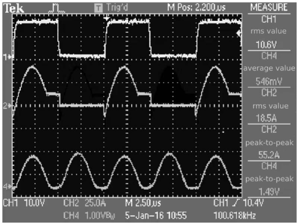 Figure 1-1 Main waveforms of half-bridge LLC converter
Next, analyze the relationship between the current flowing through the DC bus and the DC bus capacitor, and determine the effective value of the current flowing through the DC bus capacitor corresponding to the unit output power.
1.1 Working status of electrolytic capacitors—DC bus capacitor ripple current analysis when LLC resonance duration duty cycle is 0.2
Since the current waveform consists of divided sine waves and straight lines, for the convenience of analysis, the channel 2 waveform in Figure 1-1 can be divided into moments of each time segment, and the current in the LLC resonance state segment is assumed to be DC.
The current waveform that the half-bridge LLC resonant converter draws from the DC bus is shown in Figure 1-2.
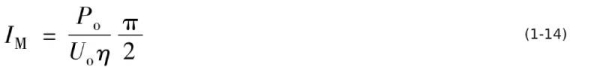
According to the waveform diagram, when the half-bridge LLC resonance duration is 20% of the switching cycle, the current leads by 18°, and the average current is
![]()
The corresponding effective current value is
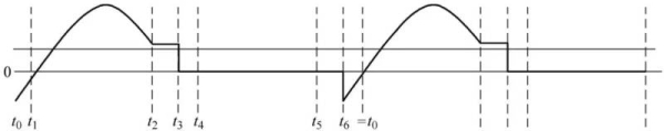
Figure 1-2 DC bus current waveform

The current flowing through the DC bus capacitor is
![]()
In the formula, IBUSav and IBUSrms are the average value of the DC bus current and the effective value of the DC bus current respectively.
Usually, the mains rectifier part of the half-bridge LLC resonant converter is a power factor correction method. If the DC bus voltage is 380V, the ripple current corresponding to the unit output power is 3.68mA. If the power factor corrected output voltage is 400V, the ripple current corresponding to unit output power is 3.5mA.
1.2 Analysis of DC bus capacitor ripple current when LLC resonance duration duty cycle is 0.25
When the half-bridge LLC resonance duration is 25% of the switching cycle, the current leads by 18°, and the average current is
![]()
The corresponding effective current value is

The current flowing through the DC-Link capacitor is
![]()
Obviously, the increase in the LLC resonance duty cycle will cause the ripple current flowing into the DC bus capacitor to increase. By only increasing the LLC resonance time duty cycle by 0.05, the ripple current increases by about 9%.
Usually, the mains rectifier part of the LLC half-bridge resonant converter is a power factor correction method. If the DC bus voltage is 380V, the ripple current corresponding to the unit output power is 5.73mA/W. If the power factor corrected output voltage is 400V, the ripple current corresponding to unit output power is 5.44mA/W.
Working status of electrolytic capacitors -The above is the analysis of the ripple current generated by the half-bridge LLC resonant converter.
2 Working status of electrolytic capacitors-ripple current generated by LLC full-bridge resonant converter
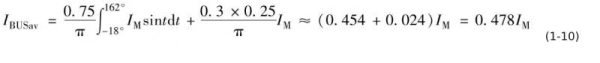
In each switching cycle of the half-bridge LLC converter, there will be half a cycle that is independent of the DC bus, and the resonant capacitor provides output power and resonant energy. Therefore, in the current that the half-bridge LLC resonant converter draws from the DC bus, the AC component will be very large. In order to reduce this DC component, the full-bridge LLC resonant converter circuit topology can be used. The waveform of channel 2 in Figure 1-3 is the current waveform obtained from the DC bus by the full-bridge LLC resonant converter.
As can be seen from Figure 1-3, compared with the half-bridge LLC resonant converter, the current waveform that the full-bridge LLC resonant converter draws from the DC bus does not have the negative half-cycle power of the half-bridge LLC resonant converter, which is provided by the resonant capacitor. The phenomenon becomes that both the positive half cycle and the negative half cycle are provided with electric energy by the DC bus.
According to the waveform diagram, it can be seen that under the same current amplitude condition, the average current obtained by the full-bridge LLC resonant converter from the DC bus doubles, that is, the output power doubles, and the effective current value becomes √2 times. Under the corresponding unit output power condition, the effective value of the AC current component flowing through the DC-Link capacitor is greatly reduced compared to the half-bridge LLC resonant converter.
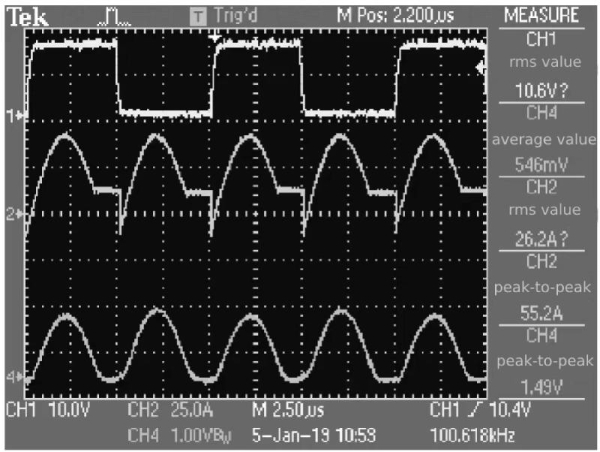 Figure 1-3 Main waveforms of full-bridge LLC resonant converter
Under the conditions of a duty cycle of 0.75 and the same output power, the corresponding current of the 380V DC bus is 4.46mA/W, and the corresponding current of the 400V DC bus is 4.23mA/W. Under unit output power conditions, the effective value of the current flowing through the DC-Link capacitor in the full-bridge LLC resonant converter is 78% of the effective value of the current flowing through the DC-Link capacitor in the half-bridge LCC resonant converter.
2.1 Working status of electrolytic capacitors—DC bus capacitor ripple current distribution when LLC resonance duration duty cycle is 0.2
When the LLC resonance time is 20% of the switching cycle, the current leads by 18°, and the average current is
![]()
The corresponding effective current value is

The current flowing through the DC bus capacitor is
![]()
Usually, the mains rectifier part of the LLC full-bridge resonant converter is a power factor correction method. If the DC bus voltage is 380V, the ripple current corresponding to the unit output power is 1.84mA/W. If the power factor corrected output voltage is 400V, the ripple current corresponding to unit output power is 1.75mA/W.
Obviously, under unit output power conditions, the ripple current flowing through the DC bus capacitor of the full-bridge LLC resonant converter is 1/2 of the DC bus capacitor of the half-bridge LLC resonant converter.
2.2 Analysis of DC bus capacitor ripple current when LLC resonance duration duty cycle is 0.25
When the half-bridge LLC resonance duration is 25% of the switching cycle, the current leads by 18°, and the average current is
The corresponding effective current value is

The current flowing through the DC bus capacitor is
![]()
Obviously, the increase in the LLC resonance duty cycle will cause the ripple current flowing into the DC bus capacitor. The increase only increases the LLC resonance time duty cycle by 0.05, and the ripple current increases by 38.2%.
Usually, the mains rectification part of the LLC full-bridge resonant converter is a power factor correction method. If the corresponding rectification DC bus voltage is 380V, the corresponding ripple current per unit output power is 2.55mA/W. If the power factor corrected output voltage is 400V, the ripple current corresponding to unit output power is 2.42mA/W.
2.3 Ripple current generated by quasi-fully resonant bridge converter
The optimal working state of the LLC resonant converter is the quasi-full resonant operating mode, which allows the converter to provide power to the output with the largest possible duty cycle while ensuring the zero-voltage turn-on condition of the switching tube. In this mode, the efficiency of the LLC resonant converter is relatively highest. The main waveforms are shown in Figure 1-4.
As can be seen from Figure 1-4, the current waveform flowing through the DC bus capacitor is close to the “absolute value” sine wave, and the sine wave analysis result can be approximated as the actual operating current. Figure 1-4 Main waveforms of quasi-full resonant full-bridge converter
The current required by the quasi-full resonant converter from the rectifier and filter circuit is

The relationship between the current peak value, the output power Po and the DC bus voltage Uo is
In the formula, eta is the converter efficiency.
The corresponding effective current value is
It can be seen from the circuit principle that the ratio of the effective value to the average value of the absolute sine function is 1.11. The effective value of the current flowing through the corresponding DC bus capacitor is
![]()
If the DC input voltage of the converter is 400V, the effective value of the DC bus capacitor ripple current per unit output power is 1.2mA/W; if the DC input voltage is 380V, the effective value of the DC bus capacitor ripple current per unit output power is 1.26mA. /W.
If it is a half-bridge quasi-full resonant converter, the DC input voltage is 400V, the effective value of the DC bus capacitor ripple current per unit output power is 2.4mA/W; if the DC input voltage is 380V, the DC bus capacitor ripple current per unit output power The effective current value is 2.52mA/W.
2.4 Summary
To sum up, the closer the LC resonance period of the bridge LLC resonant converter is to 1 in the entire switching cycle, the smaller the effective value of the current flowing through the DC bus capacitor per unit output power is. Therefore, unless there are special circumstances, the smaller the proportion of the LLC resonance mode in the switching cycle, the better, as long as the switching tube can be maintained at zero voltage.
In the full-bridge LLC resonant converter, the effective value of the current flowing through the DC bus capacitor per unit output power is 1/2 of that of the half-bridge LLC resonant converter.
Working status of electrolytic capacitors -The above is the analysis of the ripple current generated by the LLC full-bridge resonant converter.
3 Working status of electrolytic capacitors—Ripple current of output capacitor of single LLC converter
LLC resonant converter During LLC resonance, the converter does not provide power to the output end, and the output filter capacitor releases (discharges) the stored energy to provide power to the load.
Therefore, there will be no LLC resonant current part in the output ripple current analysis of the LLC resonant converter, replaced by zero current.
3.1 Working status of electrolytic capacitors—Analysis of output capacitor ripple current when LLC resonance duration duty cycle is 0
When the LLC resonance duration duty cycle is 0, the output current waveform of the full-bridge LLC converter is shown in Figure 1-5. Channel 4 in the figure is the output rectifier current waveform.
As can be seen from Figure 1-5, at the highest operating frequency of the full-bridge LLC converter, the LLC resonance process only needs to maintain the zero-voltage turn-on of the switching tube and the reverse recovery process of the output rectifier. Therefore, the LLC resonance process can be designed very carefully. short, making the LLC resonant converter operate close to the full resonant operating mode. The corresponding output rectified current closely approximates an absolute sine wave. Therefore, absolute value sine wave current analysis is used.
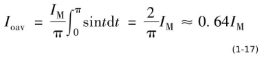
The relationship between the average current and the peak current is
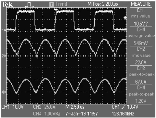 Figure 1-5 Full-bridge LLC converter output current waveform when LLC resonance duration duty cycle is 0
 The relationship between the current effective value and the current peak value is

Deduct the effective value of the rectifier output current to obtain the current flowing through the output rectifier filter capacitor as

3.2 Analysis of output capacitor ripple current when LLC resonance duration duty cycle is 0.2
The output current waveform of LLC half-bridge resonant converter is shown in Figure 1-6.
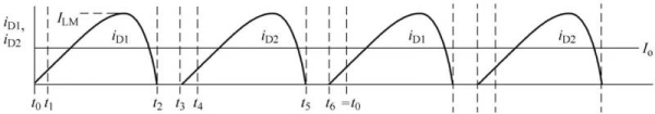 Figure 1-6 Output current waveform of LLC half-bridge resonant converter
In order to simplify the analysis, it can be considered that the combination of the diode current waveform sine wave and the dead zone produces an error within the allowable range of numerical analysis. The effective value of the output current is
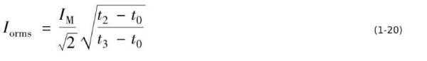
When the dead zone is 20% of the entire cycle, equation (1-20) becomes
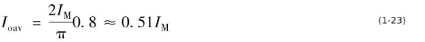
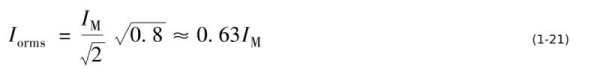 The corresponding average output current is
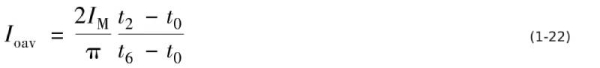
Similarly, when the dead zone is 20% of the entire cycle, equation (1-22) becomes
The current flowing through the output rectifier filter capacitor is
![]()
3.3 Analysis of output capacitor ripple current when LLC resonance duration duty cycle is 0.25
For the LLC resonant converter in constant voltage/constant current mode, the output voltage range can reach 75% to 100%, so the LLC resonance duration duty cycle will reach 0.25.
When the dead zone is 25% of the entire cycle, the effective value of the output current of the corresponding output rectifier is
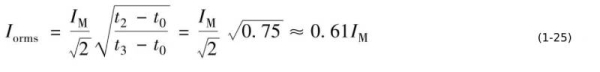 The corresponding average output current is
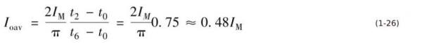
The current flowing through the output rectifier filter capacitor is
![]()
Obviously, the shorter the LLC resonance duration, the smaller the effective value of the current flowing into the output rectifier filter capacitor relative to the average output current; under the condition that the average output current is the same, the longer the LLC resonance duration, the smaller the effective value of the current flowing into the output rectifier filter capacitor. The larger the effective current value.
Working status of electrolytic capacitors—the above is the analysis of the ripple current of the output capacitor of a single LLC converter
Summarize:
Working status of electrolytic capacitors—This article mainly talks about the ripple current of the output capacitors of half-bridge LLC, full-bridge LLC and single-channel LLC converters.For more information on electrolytic capacitors, please click:https://solidcapacitor.com