1. Analysis of electrolytic capacitors–Classification
1.1 Analysis of electrolytic capacitors- Classification by material
Analysis of electrolytic capacitors-Electrolytic capacitors are classified according to positive electrode materials, including aluminum electrolytic capacitors and tantalum electrolytic capacitors.The positive electrode of an aluminum electrolytic capacitor is an aluminum corroded foil. The positive electrode of most current high-voltage electrolytic capacitors, low-voltage electrolytic capacitors, and solid polymer electrolytic capacitors is aluminum foil. Tantalum electrolytic capacitors (the positive electrode material is tantalum) include liquid tantalum electrolytic capacitors, solid tantalum electrolytic capacitors, and polymer conductive polymer tantalum electrolytic capacitors. Also belonging to the category of tantalum electrolytic capacitors are niobium electrolytic capacitors, with the positive electrode material being niobium.
Electrolytic capacitors are classified according to negative electrode materials, including liquid aluminum electrolytic capacitors, liquid tantalum electrolytic capacitors, solid aluminum electrolytic capacitors, and solid tantalum electrolytic capacitors.
The negative electrode of an electrolytic capacitor can be an electrolyte, such as a liquid aluminum electrolytic capacitor and a liquid tantalum electrolytic capacitor. The simplest and most effective way to make close contact with the oxide film of the positive electrode foil is to apply a conductive electrolyte. An electrode plate is required to lead out the negative electrode. Liquid aluminum electrolytic capacitors use negative electrode foil to lead out the negative electrode, and liquid tantalum electrolytic capacitors use a shell to lead out.
The negative electrode of solid tantalum electrolytic capacitors is made of manganese dioxide, and graphite and a lead-out electrode are used to lead out the negative electrode; the negative electrode of solid aluminum electrolytic capacitors is made of polymer conductive polymer, and the negative electrode is led out by filtering. Tantalum electrolytic capacitors can also use polymer conductive polymers as the negative
This is the Analysis of electrolytic capacitors – classification by material
1.2 Analysis of electrolytic capacitors-Classification by package
Paper tube electrolytic capacitors are electrolytic capacitors suitable for electronic tube products before the 1970s. They are encapsulated by wax paper tubes and epoxy resin. Compared with current electrolytic capacitors, they are large in size, poor in performance, and short in life. They have withdrawn from the stage of history along with electronic tube products.
Bolt type electrolytic capacitor is a large electrolytic capacitor with an outer diameter of 36~101mm and a length of 53~240mm.
Low-voltage bolt-type electrolytic capacitors can reach 3F/6.3V, and high-voltage capacitors can reach 2200μF/450V.
Since bolt-type aluminum electrolytic capacitors need to flow a large current and generate large amounts of heat, aluminum electrolytic capacitors are electronic components that have relatively difficult heat conduction. In order to improve heat dissipation, it is necessary to remove the heat from the center part of the core of the electrolytic capacitor, which has the highest temperature. The core can be assembled in a special shell with a central heat conduction hole. During use, the heat dissipation rod can be inserted into the heat dissipation hole to help the electrolytic capacitor. heat dissipation. The bolt-type electrolytic capacitor into which the heat sink rod can be inserted is shown in Figure 1-1.
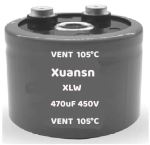
Figure 1-1 Bolt-type electrolytic capacitor with heat sink insertable
Electrolytic capacitors are polarized capacitors, and the polarity cannot be reversed during use. Since the two pins of aluminum electrolytic capacitors have the same shape, they may be plugged in reverse when assembled on the circuit board. The “fool-proof” design of the plug-in capacitor Aluminum electrolytic capacitors can prevent polarity reversal, as shown in Figure 1-10.
Guide pin electrolytic capacitors are small electrolytic capacitors with a minimum diameter of 3mm, a maximum diameter of 25mm, and a length of 8 to 60mm, as shown in Figures 1-4 to 1-6.
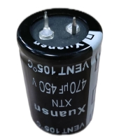
Figure 1-2 Chunky pin-type aluminum electrolytic capacitor
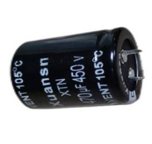
Figure 1-3 Two-pin pin-type aluminum electrolytic capacitor
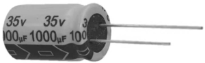
Figure 1-4 General size lead pin aluminum electrolytic capacitor
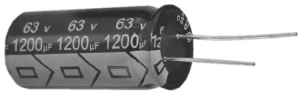
Figure 1-5 Large size lead pin aluminum electrolytic capacitor
Figure 1-6 Slim lead pin aluminum electrolytic capacitor
The capacitance range of lead-pin electrolytic capacitors is 1~22000μF.
Surface mount electrolytic capacitors can be directly mounted on the circuit board. Unlike lead-type and pin-type electrolytic capacitors, which insert the electrode pins through preset holes on the circuit board and weld them, they can be directly mounted on the surface of the circuit board. , without passing through the circuit board, can greatly reduce the space occupied by the circuit board, as shown in Figure 1-2 and Figure 1-3.
At the end of the 20th century, Germany defined cars as “electronic products”, and electrolytic capacitors are indispensable in electronic circuits, so electrolytic capacitors are also indispensable in cars. Factors such as the need for cars to drive under various road conditions and engine operation make it inevitable that cars will vibrate. However, general electrolytic capacitors do not consider vibration requirements when they are designed and manufactured, so they cannot meet the vibration requirements of car regulations when installed on cars. Therefore, the demand for electrolytic capacitors in automobiles has given rise to “automotive grade” electrolytic capacitors.
The characteristic of the appearance of automotive-grade electrolytic capacitors is that the outer casing has a “girdle” that fixes the core and outer casing of the electrolytic capacitor. Another feature is the axial lead pattern of small electrolytic capacitors. When the electrolytic capacitor is slightly larger or needs to be installed vertically, the guide-pin packaging method of the lead on the same side only relies on the guide pins to fix the electrolytic capacitor to the circuit board and cannot pass the vibration test. Therefore, multiple pins of the shell need to be used to fix the electrolytic capacitor on the circuit board. This kind of package is commonly known as “crown type” electrolytic capacitor.
The appearance of automotive grade axial lead type electrolytic capacitor and crown type electrolytic capacitor are shown in Figure 1-7 and Figure 1-8.

Figure 1-7 Automotive grade axial leaded electrolytic capacitor
This is the Analysis of electrolytic capacitors – classified by package
1.3 Analysis of electrolytic capacitors-Classification by use
1.3.1 General-purpose electrolytic capacitors General-purpose electrolytic capacitors were once the most common electrolytic capacitors and can be used in most electronic products. Its typical models include the CD03 series and the improved small-volume CD110 series. Since the CD110 series is designed for 50/60Hz alternating current rectification and filtering applications and other applications of general electronic circuits, with the widespread use of power electronics technology today, its performance has been difficult to meet the performance requirements of various switching power supplies, and electrolytic capacitors Industrial applications are also changing with each passing day, so the application of new electrolytic capacitors has become inevitable.
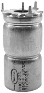
Figure 1-8 Automotive grade crown type electrolytic capacitor
1.3.2 Industrial electrolytic capacitors Modern power electronics technology has promoted the development of frequency converters, and 380V and 660V three-phase AC input frequency converters require high-voltage and large-capacity filter capacitors, bolt-type high-voltage electrolytic capacitors and large-capacity pin type High voltage electrolytic capacitors are widely used.
In various industrial applications, in addition to frequency converters, industrial electrolytic capacitors also have industrial applications such as photovoltaic inverters, wind power inverters, and inverter arc welding power supplies.
Compared with electrolytic capacitors for general applications, industrial electrolytic capacitors require higher reliability and longer life.
Switching power supply electrolytic capacitors:
In the 1970s, switching power supplies began to be applied, from computer power supplies to communication power supplies and TV power supplies, and now switching power supplies have replaced most linear regulated power supplies, as well as today’s notebook computer power adapters and various mobile phone chargers. And various types of power adapters, etc. They became the main users for small electrolytic capacitor applications.
Switching power supply is a voltage/stabilized current power supply in the working mode of power semiconductor devices. It is widely used in industry, military, commerce, and daily life. It has become an indispensable electronic equipment or device.
The main requirements for electrolytic capacitors in switching power supplies are: small size, good high-frequency characteristics, and good ripple current tolerance. It is difficult for general-purpose electrolytic capacitors to adapt to such performance requirements. Therefore, pin-type high-voltage electrolytic capacitors and high-frequency low-resistance electrolytic capacitors required for televisions and switching power supplies have emerged. At the same time, the maximum operating temperature and lifespan have been improved.
1.3.3 Lighting electrolytic capacitors Electronic technology has entered the lighting field, allowing energy-saving lamps to largely replace incandescent lamps. Energy-saving lamps require one or two high-voltage electrolytic capacitors. The characteristics of electrolytic capacitors for energy-saving lamps are high temperature, long life and high ripple current resistance, such as 105℃/10000h.
With the extensive application of LEDs for lighting, LED lamps have gradually replaced energy-saving lamps. At this time, electrolytic capacitors for lighting need to be smaller in size and have a higher operating temperature such as 130°C based on electrolytic capacitors for energy-saving lamps. Not only high-voltage electrolytic capacitors, but also low-voltage electrolytic capacitors are required for LED drivers, and the maximum operating temperature of high-voltage electrolytic capacitors must also be achieved.
1.3.4 Electrolytic capacitors for mobile phone chargers With the widespread use of smartphones, the demand for mobile phone chargers has also increased significantly. The entry-level charging capacity of mobile phone chargers is 5V/2A. In recent years, fast charging modes have appeared, and the charger power has reached 40W, 65W or even 120W. Among them, not only high-voltage electrolytic capacitors are needed, but also low-voltage electrolytic capacitors with high ripple current resistance are needed. The ripple current resistance often reaches 3~5A. Such electrolytic capacitors can only be solid aluminum electrolytic capacitors. The large demand for solid aluminum electrolytic capacitors in mobile phone chargers (a mobile phone charger requires at least two solid aluminum electrolytic capacitors) has led to the rapid development of solid aluminum electrolytic capacitors in my country after 2014.
1.3.5 Electrolytic capacitors for home appliances The main force of electrolytic capacitors for home appliances is air conditioners. After variable frequency air conditioners became the mainstream of air conditioners, electrolytic capacitors entered the field of air conditioners. The main board of the air conditioner is generally placed inside the plug-in unit. The working environment is harsh, with temperatures reaching over 55°C, and the humidity may remain above 85% for a long time. In this environment, the high temperature resistance and humidity resistance of electrolytic capacitors are the performance requirements of air conditioning electrolytic capacitors.
1.3.6 Automotive electrolytic capacitors As more and more automotive electronic equipment becomes available, the demand for automotive electrolytic capacitors has also increased significantly. Compared with fixed or portable electronic equipment, automotive electronics need to withstand vibration testing. Considering the reliability of automotive electronics, automotive electrolytic capacitors must be “automotive grade” electrolytic capacitors. Automotive electrolytic capacitors need to meet the wide temperature range of “vehicle regulations”, with the most severe part being -40 to 120°C
This is the Analysis of electrolytic capacitors – classified by use
2. Analysis of electrolytic capacitors–Original definition of technical data
After World War II, the United States became the world’s science and technology center and had the right to speak in science and technology. Many rules for electronic components were mostly formulated by the United States. For example, the pin spacing of dual in-line integrated circuits is a multiple of 0.1in (1in=0.0254m). . Since the U.S. power grid frequency is 60Hz, 60Hz is also selected as the test condition for electronic devices. Most of the characteristics of electrolytic capacitors are tested under 60Hz or an integer multiple of 60Hz.
The initial electrolytic capacitors were used for filtering after AC rectification and had few other uses. Therefore, the parameters of electrolytic capacitors were mainly tested under ideal rectification and filtering conditions, that is, under 120Hz conditions.
The technical data of aluminum electrolytic capacitors in the tube era mainly include five parameters: overall dimensions, rated voltage, capacitance, loss factor, and leakage current. As the application field of electrolytic capacitors expands to the field of power electronics and becomes the most important application field, Merely marking these five parameters is not enough; more technical data is needed.
This is the Analysis of electrolytic capacitors–Original definition of technical data
3. Analysis of electrolytic capacitors–appearance
Nowadays, aluminum electrolytic capacitors are usually cylindrical, and the main external dimensions include diameter and height, electrode lead-out method and electrode size.
The dimensions of European-style axial lead aluminum electrolytic capacitors are shown in Figure 1-9.
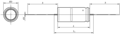
Figure 1-9 Dimensions of axial leaded aluminum electrolytic capacitors
The dimensions of the same-side leaded aluminum electrolytic capacitor are shown in Figure 1-10.
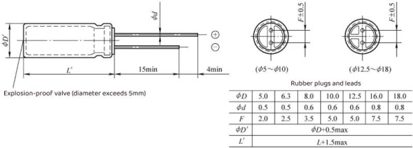
Figure 1-10 Dimensions of same-side leaded aluminum electrolytic capacitors
The dimensions of pin type aluminum electrolytic capacitors are shown in Figure 1-11
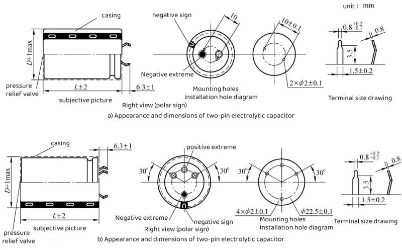
Figure 1-11 Dimensions of pin-type aluminum electrolytic capacitors
The dimensions of bolt-type aluminum electrolytic capacitors are shown in Figure 1-12.
The dimensions of the welded lug aluminum electrolytic capacitor are shown in Figure 1-13.
The dimensions of surface mount aluminum electrolytic capacitors are shown in Figure 1-14.
This is the Analysis of electrolytic capacitors – appearance.
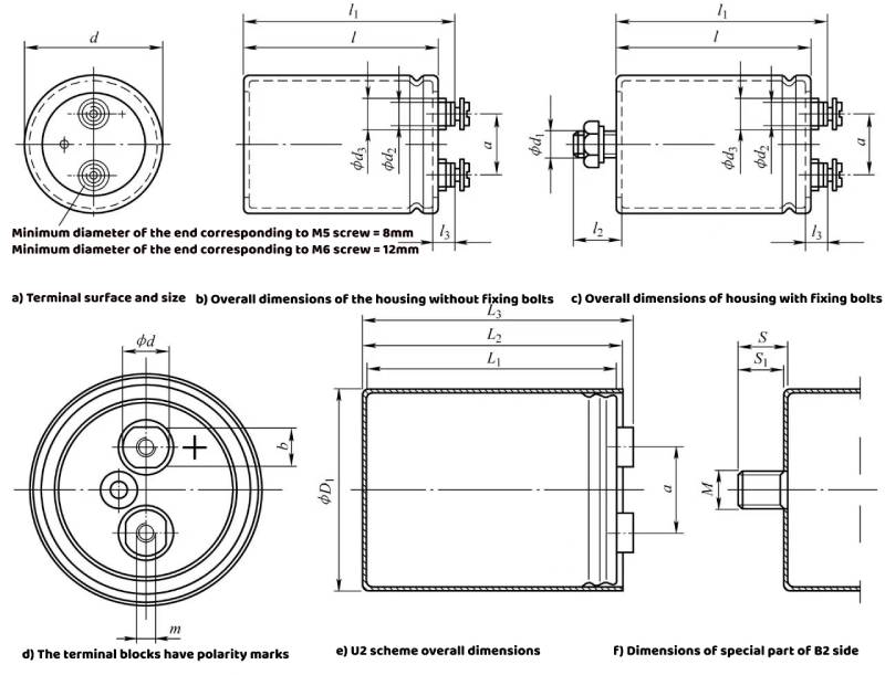
Figure 1-12 Dimensional representation of bolt-type aluminum electrolytic capacitors
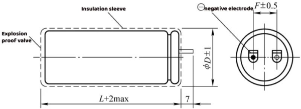
Figure 1-13 Dimensional representation of solder tab aluminum electrolytic capacitors
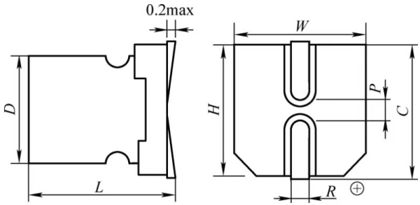
Figure 1-14 Dimensions of surface mount aluminum electrolytic capacitors
4.Analysis of electrolytic capacitors–Appearance and polarity marking method
Since electrolytic capacitors have polarity and cannot be connected in reverse, you need to know the polarity of the electrolytic capacitor electrodes from the outer package. Electrolytic capacitors have obvious polarity signs on their appearance. The polarity marking method of small electrolytic capacitors is shown in Figure 1-15.
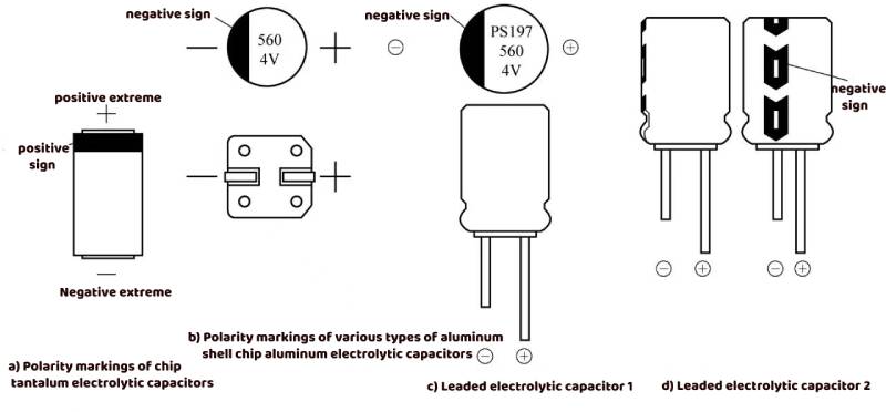
Figure 1-15 Polarity marking method of small electrolytic capacitors
Figure 1-15a is a resin-encapsulated chip tantalum electrolytic capacitor. It should be noted that the polarity mark of aluminum electrolytic capacitors and solid aluminum electrolytic capacitors is different. The polarity mark of tantalum electrolytic capacitors is positive, while aluminum electrolytic capacitors and solid state The polarity mark of aluminum electrolytic capacitors is negative, which must be paid attention to during application.
Figure 1-15b shows a chip aluminum electrolytic capacitor or a solid aluminum electrolytic capacitor. The chip aluminum electrolytic capacitor not only has an obvious negative polarity mark on the top of the capacitor, but also has a notch on the base that is the positive polarity end.
Figure 1-15c and d are leaded aluminum electrolytic capacitors or leaded solid aluminum electrolytic capacitors. The long lead of the leaded electrolytic capacitor is the positive electrode, and there is an obvious negative mark (minus sign) on the plastic heat shrink tube. For some leaded electrolytic capacitors that require good heat dissipation, when heat shrinkable tubes cannot be used for better heat dissipation or for patch packaging, there is usually an obvious negative electrode indicator mark on the top of the capacitor, as shown in Figure 1-15c.
Pin-type electrolytic capacitors are also marked with positive and negative pole marks on the rivets of their leads. Some have pits pressed on the rivets as the negative pole mark, and the negative pole mark is printed on the plastic sleeve, as shown in Figure 1-16b and c. Show.
It should be noted that in order to obtain good fixing performance, relatively large pin-type electrolytic capacitors are usually made with four pins, as shown in Figure 1-16c. One of the four pins is the positive pole, one is the negative pole, and the other two are empty legs. However, in terms of electrical connection, these two empty legs must not be connected to the positive pole, but can be connected to the negative pole. The reason is If these two empty legs are in contact with the electrolyte in the electrolytic capacitor, they are equivalent to the negative electrode.
Bolt-type electrolytic capacitors have positive and negative pole marks on the cover, but there are no positive and negative pole marks on the plastic sleeve, as shown in Figure 1-16a.
This is the Analysis of electrolytic capacitors – appearance and polarity marking method
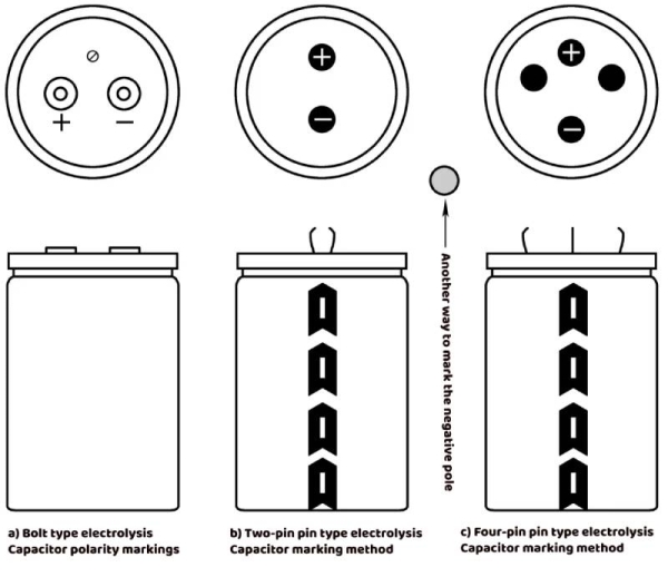
Figure 1-16 Polarity marking method of large aluminum electrolytic capacitors
5. Analysis of electrolytic capacitors–Parameter identification of electrolytic capacitors
Usually, in addition to the negative electrode mark on the electrolytic capacitor, there is also the manufacturer’s registered trademark, temperature range, capacitance, rated voltage, and model number of the electrolytic capacitor, as shown in Figure 1-17.
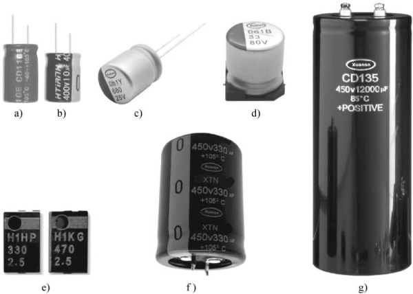
Figure 1-17 Parameter marking methods of electrolytic capacitors in various packages
Figure 1-17a and b are guide pin liquid electrolytic capacitors. The information of the electrolytic capacitor is printed on the casing, with the manufacturer’s trademark, model, rated voltage, capacitance, operating temperature range, negative electrode mark, and some also There is a production batch number.
Figure 1-17c and d are guide pin type solid aluminum electrolytic capacitors. All information is printed on the casing, marked with the manufacturer’s trademark, model, rated voltage, capacitance (in μF), negative electrode mark, and some also There is a production batch number.
Figure 1-17e shows a laminated solid aluminum electrolytic capacitor, which is encapsulated in resin. The shell is marked with the model, rated voltage, capacitance (in μF), negative electrode mark, etc.
Figure 1-17f shows a pin-type electrolytic capacitor. The information is printed on the sleeve, with the manufacturer’s trademark, model, rated voltage, capacitance, operating temperature range, negative electrode mark, and sometimes the production batch number.
Figure 1-17g shows a bolt-type electrolytic capacitor. The information is also printed on the sleeve. It is marked with the manufacturer’s trademark, model, rated voltage, capacitance, and operating temperature range. The positive electrode is marked with a “+” sign, and some also have Production batch.
This is the Analysis of electrolytic capacitor-parameter identification
6.Analysis of electrolytic capacitors–Voltage parameters
The voltage indicators of aluminum electrolytic capacitors mainly include formation voltage, flash voltage, aging voltage, rated DC voltage, rated surge voltage, instant overvoltage and reverse voltage, which will be introduced one by one below.
6.1 Analysis of electrolytic capacitors-Positive foil formation voltage
The formation voltage is the voltage applied to the positive electrode foil of the aluminum electrolytic capacitor during the formation process. It is the highest among the voltage indicators of the aluminum electrolytic capacitor. For example, an aluminum electrolytic capacitor with a rated voltage of 400V requires a forming foil with a forming voltage of 530V or higher. The longer the life, the higher the formation voltage required. Some manufacturers choose 480V formation foil for short-life (such as 2000h life) aluminum electrolytic capacitors to reduce cost and volume.
So, does the formation voltage have any characteristics? some!
If the formation voltage is achieved at room temperature, then after being made into an electrolytic capacitor, the electrolytic capacitor will have insufficient high temperature withstand voltage.
Through testing, it can be known that the withstand voltage value of the formed foil formed at 85°C at 105°C is only 70% to 80% of the formed voltage at 85°C. It can be inferred from this that whether the withstand voltage value will drop to 60% of the formation voltage at 125°C, and whether it will drop to 40% of the formation voltage at 145°C? This needs to be verified through testing, but it must be acknowledged that as the temperature of the capacitor core is higher than the formation temperature, the withstand voltage of the aluminum oxide film will decrease, possibly by a larger amount.
Normally, the formation voltage required by an electrolytic capacitor at 105°C is about 1.32 (1.152) times the rated voltage. The formation voltage of an electrolytic capacitor with a rated voltage of 400V is 529V, which is about 530V. This is the basis for electrolytic capacitors with a rated voltage of 400V to be foiled at 530V.
If it is under 85°C conditions, the electrolytic capacitor requires 1.15 times the rated voltage of the formed foil, that is, the formed foil voltage corresponding to 460V is at least 480V. In other words, 480V formed foil can also make electrolytic capacitors with a rated voltage of 400V, but it is only limited to products with a temperature of 85°C and a lifespan of 2000h or 1000h.
6.2 Analysis of electrolytic capacitors-Flash voltage
Flash voltage is an electrical property of the electrolyte. The electrolyte is conductive, but flash fire is not allowed when an aging voltage is applied between two aluminum electrodes without an oxide layer, which will cause the electrolytic capacitor to fail or even burn.
In order to prevent the electrolyte from flashing under normal voltage, a flash-preventing additive (long-chain polymer) needs to be added to the electrolyte. The higher the flashing voltage, the longer the polymer chain, and the more viscous the corresponding electrolyte. Therefore, the time for the core of high-voltage electrolytic capacitors to be impregnated with electrolyte is much longer than that of low-voltage electrolytic capacitors, and even pressure impregnation is required.
The flash voltage of the electrolyte needs to be higher than the high temperature aging voltage and lower than the formation voltage of the positive electrode foil. There is no need for the flash voltage of the electrolyte to be higher than the formation voltage of the positive electrode foil, and it is a waste to overuse materials.
6.3Analysis of electrolytic capacitors-Aging voltage
Aging voltage is the voltage required to repair the damaged oxide film of aluminum electrolytic capacitors after nailing, impregnation, and assembly. This repair process is called aging. The aging voltages of different aging processes are also different.
6.3.1 Analysis of electrolytic capacitors-Room temperature aging
Normal temperature aging is an aging process performed in a normal temperature environment to repair the oxide film damaged during the manufacturing process. This repair process is completed in the electrolyte. In order to reduce the manufacturing cost of electrolytic capacitors and increase the manufacturing speed, the usual aging process is to assemble or seal the electrolytic capacitors and then age them.
In order to effectively repair the damaged oxide film, an appropriate amount of oxidant needs to be added to the electrolyte to oxidize the exposed aluminum on the positive electrode foil and the alumina part with insufficient voltage resistance.
The aging process consumes the components of the electrolyte contained in the assembled or sealed electrolytic capacitors. During aging, hydrogen and other gases will also be produced. If these gases are not absorbed, the aging process will cause the electrolytic capacitor shell to bulge, especially Open the explosion-proof valve to render the electrolytic capacitor useless. Therefore, it is necessary to add a getter (or hydrogen scavenger) to the electrolyte. In order for the hydrogen scavenger to work effectively and to ensure the performance of the electrolyte and the life of the electrolytic capacitor, the aging current needs to be limited to a certain range.
6.3.2 Analysis of electrolytic capacitors-High temperature aging
After aging at room temperature, why does it need to be aged at high temperature? The main reason is that the aluminum oxide film produced by aging at room temperature is “hydrated alumina”, which contains aluminum hydroxide component, that is, “hydrated” alumina. Part or most of it needs to be converted into “anhydrous” during the high-temperature aging process. “Alumina.
The second reason may be that the voltage resistance characteristics of alumina are related to temperature. As the temperature increases, the voltage resistance of alumina decreases. Therefore, the alumina part aged at room temperature may not have enough withstand voltage at high temperatures, and it needs to be aged again at the highest operating temperature to make the repaired oxide film meet the voltage withstand requirements at high temperatures.
Today’s 105℃/400V aluminum electrolytic capacitors generally need to choose a formation foil with a formation voltage of 530V. The corresponding normal temperature aging voltage is 450~470V, and the high temperature aging voltage is 410~430V.
6.3.3 Analysis of electrolytic capacitors-Why not add the aging voltage to the formation voltage?
The formation voltage is the voltage of the formation tank, not necessarily the formation voltage of the formation foil. The reason is that the formation liquid in the formation tank has a high resistivity, and the formation current will produce a voltage drop in the formation liquid. Therefore, the actual formation voltage of the positive electrode foil of the electrolytic capacitor must be lower than the formation voltage of the formation tank.
Even if the aging voltage is applied to 95% of the formation voltage, it will exceed the aging voltage of the positive foil of the electrolytic capacitor, that is, the formation foil, causing the positive foil to undergo formation phenomenon under the action of the aging voltage in the packaged electrolytic capacitor case, and the electrolytic capacitor core The core will generate a large amount of gas and heat, so that the assembled aluminum electrolytic capacitor will not be able to withstand the heat and gas generated by this process. The core may be dry-packed or the bottom may be convex. In short, it cannot be aged at room temperature.
Why is the high temperature aging voltage lower than the normal temperature aging voltage? The reason is that the breakdown field strength of the aluminum oxide film decreases with increasing temperature. For example, at a high temperature aging temperature of 105°C, the formation voltage of a foil formed at a temperature of 85°C will be significantly reduced. In the actual high-temperature aging process, the applied aging voltage needs to be lower than the actual formation voltage at a temperature of 105°C. If a 125°C electrolytic capacitor is aged at 125°C, its aging voltage needs to correspond to the formation voltage at 125°C, and the voltage difference is larger than that at 105°C aging temperature. It can be seen that the higher the aging temperature, the greater the difference between the aging voltage and the nominal formation voltage of the formation foil. The lower the temperature of the formation process of the formed foil, the greater the gap.
As can be seen in the tantalum electrolytic capacitor section, the operating voltage of tantalum electrolytic capacitors decreases as the temperature increases, even to 50% of the rated voltage.
The withstand voltage at room temperature seems to be able to reach the room temperature aging voltage, but this is not an oxide film structure formed by high temperature aging, and there will be a large leakage current, so it can only be applied to operating voltages below the high temperature aging voltage.
The formation voltage of solid aluminum electrolytic capacitors is significantly higher than the rated voltage, because the temperature of the formation liquid of solid electrolytic capacitors during the “formation” process is about 70°C, which is significantly lower than the maximum operating temperature of solid electrolytic capacitors of 125°C, so the aluminum oxide film withstands voltage The alumina pressure resistance caused by the temperature difference will be significantly higher than 70~125℃.
6.4 Analysis of electrolytic capacitors-Rated voltage and operating voltage
Rated DC voltage UR is the maximum continuous operating voltage allowed by the capacitor within the rated temperature range. It includes the sum of the DC voltage and the pulse voltage or continuous pulse voltage between the two electrodes of the capacitor. Typically, the voltage rating of an aluminum electrolytic capacitor is indicated on the capacitor. Aluminum electrolytic capacitors with a rated voltage of ≤100V are low-voltage aluminum electrolytic capacitors, while those with a rated voltage of ≥150V are high-voltage aluminum electrolytic capacitors.
The nominal values of the rated voltage are 3V, 4V, 6.3V, (7.5V), 10V, 16V, 25V, 35V, (40V), 50V, 63V, 80V, 100V, 160V, 200V, 250V, 300V, (315V) , 350V, (385V), 400V, 450V, 500V, (550V). Among them, the voltage values in brackets are voltage values that are not common in my country.
The operating voltage is the continuous operating voltage allowed by the capacitor within the rated temperature range. Within the entire operating temperature range, in theory, the capacitor can operate continuously at the rated voltage (including superimposed AC voltage) or at any voltage between 0V and the rated voltage. For short periods of time, the capacitor can also withstand reverse voltages with an amplitude no higher than -1.5V.
6.5 Analysis of electrolytic capacitors-Reverse voltage
Aluminum electrolytic capacitors are polarized capacitors and are generally not allowed to operate at reverse voltage. Where necessary, reverse polarity can be prevented by connecting a diode. Typically, diodes with a conduction voltage of approximately 0.8V are used. In a time period shorter than 1 second, a reverse voltage less than or equal to 1.5V can be tolerated, but only for a short period of time and must not be in a continuous working state!
The main hazard of reverse voltage is that the reverse voltage will produce an electrochemical process that thins the aluminum oxide film, thereby damaging the aluminum electrolytic capacitor.
As the ability of aluminum electrolytic capacitors to withstand ripple current increases, when a large ripple current flows through the aluminum electrolytic capacitor, the capacitance and ESR between the electrolyte and the negative electrode foil will cause the negative electrode foil to present a positive voltage relative to the electrolyte. In order to avoid This positive voltage affects the negative electrode foil and even the entire electrolytic capacitor. The negative electrode foil of the electrolytic capacitor usually forms a formation voltage of several volts to prevent the negative electrode of the electrolytic capacitor from being formed when the ripple current is high, leading to early failure of the electrolytic capacitor.
6.6 Analysis of electrolytic capacitors-Overvoltage withstand capability
Overvoltage withstand capability can be divided into rated surge voltage US and lightning strike voltage.
The rated surge voltage US is the voltage value that the aluminum electrolytic capacitor can withstand in a short period of time. The test conditions are: the capacitor works at 25°C, the charging time does not exceed 30s, and the interval between two times is not less than 5 minutes. The relationship between surge voltage and rated voltage specified in IEC 384-4 is
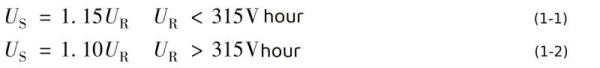
Formula Analysis of electrolytic capacitors
Some aluminum electrolytic capacitors (mainly large aluminum electrolytic capacitors) are also marked with surge voltage on the outer shell. The general marking method is: ×××US.
6.6.1 Surge voltage measurement
The specific test method for the rated surge voltage of the capacitor is: at normal room temperature, aluminum electrolytic capacitors with a capacitance of less than 2500μF can be connected in series with a resistor of 1000Ω±10%, while those with a capacitance of 2500μF or higher require a series resistor whose resistance is The value is R=2.5/C. The unit of this resistance value is MΩ; C is the capacitance in μF. During the period of 30 seconds for the voltage to be on and 4 minutes for 30 seconds to be off, each capacitor is discharged through a charging resistor or equivalent resistance. Repeat the 120h cycle. The requirements for passing the test are that the DC leakage current (DCL), equivalent series resistance (ESR) and dissipation factor (DF) values before and after the test should not change, and there are no traces of mechanical damage or electrolyte leakage.
6.6.2 The impact of surge voltage testing on electrolytic capacitors
It can be seen from this test condition that because the applied surge voltage is higher than the high temperature aging voltage, it is possible for the aluminum electrolytic capacitor to enter an “aging” state. Since the current limiting resistor is connected in series in the test circuit, the surge current corresponding to the surge voltage The final value will not be very large. For example, an aluminum electrolytic capacitor with a rated voltage of 400V has a room temperature aging voltage of 430V. According to equation (4-2), the surge voltage is 440V, which is greater than 430V. In this state, the electrolytic capacitor will Enter the “room temperature aging” state. Its current-limiting resistor limits the “aging” current to the initial value of 25mA. Since the “aging” time duty cycle is less than 1/10, the equivalent “aging” current will be less than 2.5mA. With the “aging” process, the “aging” current decreases and finally remains on the order of about 1mA. The insufficient internal air pressure of the electrolytic capacitor caused by the gas production rate causes the electrolytic capacitor to bulge.
If the electrolytic capacitor ages poorly, a relatively large “aging” current will be generated under the action of surge voltage, and a relatively large amount of gas will be generated, which may cause the electrolytic capacitor to have a convex bottom.
6.6.3 Instantaneous overvoltage
Instantaneous overvoltage refers to the ultimate overvoltage that aluminum electrolytic capacitors can generally withstand instantly. For aluminum electrolytic capacitors, instantaneous overvoltage is usually an overvoltage state that exceeds the surge voltage rating of the capacitor. This state will cause a large leakage current and enter a constant voltage state. The voltage and current characteristics are very similar to the reverse direction of a Zener diode. characteristic. If the electrolytic capacitor cannot withstand this instantaneous overvoltage, it may breakdown and fail. However, even if it can withstand it, this state must not last for a long time, because the hydrogen generated by the capacitor will cause the irreversible pressure release device to operate (explosion). Destroy aluminum electrolytic capacitors. Even if the pressure relief device does not operate, this state will consume electrolyte. Repeated occurrences of this state will shorten the service life of the aluminum electrolytic capacitor. Therefore, if it only needs a very short working life in an electronic circuit, in a sense the terminal voltage is allowed to reach the surge voltage or slightly lower than the instantaneous overvoltage.
RIFA’s test standards for instantaneous overvoltage are: sharp pulse, rise time between 100μs and 5ms; the interval between two instantaneous overvoltages is greater than 5min; it can withstand 1,000 instantaneous overvoltage impacts during its lifetime.
6.6.4 Lightning overvoltage
In order to reduce the cost of low-power switching power supplies, many manufacturers have eliminated varistors, common-mode inductors, X capacitors and even Y capacitors in low-power switching power supplies. This not only greatly reduces the cost of the switching power supply, but also reduces the size of the switching power supply. It is reduced by 1/4 to 1/3, and the overvoltage and even lightning strike functions that should be suppressed by the varistor and X capacitor are “transferred” to the electrolytic capacitor. This requires the electrolytic capacitor to have the ability to withstand lightning overvoltage.
400V electrolytic capacitors need to withstand the transient overvoltage impact of no less than X2 capacitors without failing, which is very unreasonable in the field of capacitors. For example, a general-purpose film capacitor with a rated voltage of 400V, or even a general-purpose film capacitor with a rated voltage of 630V, will never pass the 2.5kV transient overvoltage test, so there are more expensive X2 capacitors. As general-purpose aluminum electrolytic capacitors with a rated voltage of 400V, they need to pass the 3kV or even 6kV lightning voltage (equivalent to transient overvoltage) test that customers hope to pass. This is extremely unfair to electrolytic capacitors. However, the aluminum electrolytic capacitor did pass the lightning strike test, indicating that the aluminum electrolytic capacitor has extremely excellent transient overvoltage withstand characteristics, which is due to the formation characteristics of the aluminum oxide film of the aluminum electrolytic capacitor.
For electrolytic capacitors to pass the lightning overvoltage resistance test, such as the 3000V lightning voltage resistance test, the electrolytic capacitor needs to be well aged and have no aging defects. Otherwise, lightning overvoltage will produce a large amount of gas at the aging defects, causing the electrolytic capacitor to bulge, and even the aging defects will be breakdown.
6.6.5 AC superposition, ripple voltage
Not only can DC voltage be applied between the two ends of the aluminum electrolytic capacitor, but also AC voltage such as ripple voltage can be superimposed on the applied DC voltage, but the following conditions must be met:
1.6.6.5.1 The sum of DC voltage, AC superimposed voltage and ripple voltage does not exceed the rated voltage, and reverse polarity does not occur.
1.6.6.5.2 The effective value of the ripple current flowing through the electrolytic capacitor shall not exceed the rated ripple current.
This is the Analysis of electrolytic capacitors – voltage parameters
7. Analysis of electrolytic capacitors— capacitance
The capacitance indicators of aluminum electrolytic capacitors mainly include rated capacitance, electrostatic capacitance and tolerance range of capacitance measurement.
7.1 Analysis of electrolytic capacitors-Rated capacitance
Rated capacitance is the nominal capacitance, defined when tested at 120Hz/25℃. The rated capacitance is the single capacitance. Most of the nominal capacitances are the preferred values of the E12 series, namely 1.0, 1.2, 1.5, 1.8, 2.2, 2.7, 3.3, 3.9, 4.7, 5.6, 6.8, 8.2. There are also special rated capacitances, such as 8000μF.
7.2 Analysis of electrolytic capacitors-Electrostatic capacitance
Electrostatic capacitance, that is, DC capacitance, is obtained by measuring the charge of a capacitor when a DC voltage is applied to it. At normal temperature, its value is slightly larger than that of AC, and it has superior stability characteristics.
7.3 Analysis of electrolytic capacitors-Capacitance measurement
The capacitance of a capacitor can be obtained by testing its AC impedance or the amount of charge it can hold at a DC voltage, with the two methods producing slightly different results. Generally speaking, the capacitance measured by the DC voltage test method (DC capacitance) is slightly higher than the capacitance measured by the AC current method (AC capacitance).
In order to be consistent with the conditions of the most common applications (such as rectification, filtering or DC coupling), the most common test frequency for the AC capacitance of aluminum electrolytic capacitors is generally 2 times the power frequency AC of 50Hz or 60Hz, that is, IEC 384-1, IEC 100Hz or 120Hz given by 384-4. This result is measured using the special test methods given in IEC 384-1 and IEC 384-4.
An AC voltage less than or equal to 0.5V (which will not cause reverse breakdown of the aluminum electrolytic capacitor) can be applied to the aluminum electrolytic capacitor to detect the capacitor current. The capacitance can be determined according to C=I/(2πfU). The change of AC capacitance with temperature may be greater than 10%, and it also decreases with the increase of frequency. Therefore, IEC 384-1 and IEC 384-4 give the basic test conditions when the frequency is 100Hz or 120Hz and the temperature is 20℃. You can also use the test method of testing the capacitance of general capacitors, using a bridge circuit to test the capacitance to apply 1Vrms on the power supply side. The maximum AC signal voltage is a 120Hz sine wave with no DC forward bias voltage and no high-order harmonics and sub-harmonics. Although the peak value of the power supply voltage is close to 1.5V, through the voltage division of the bridge circuit, the peak voltage applied to the aluminum electrolytic capacitor will be lower than 1V, which will not cause damage to the aluminum electrolytic capacitor. Generally speaking, aluminum electrolytic capacitors are mostly used for filtering, bypassing and DC coupling after rectification. These applications do not have high requirements on the value and accuracy of the capacitance. A capacitance tolerance (accuracy) of ±20% can satisfy the requirements well. Require.
In some applications (such as discharge circuits and timing circuits), the DC capacitance plays a decisive role. This requires measuring DC capacitance, which can usually be measured in a charge/discharge manner. According to C=It/ΔUC, constant current charge/discharge is used, and the capacitance C is obtained by detecting the time t. Considering that the leakage current of electrolytic capacitors is not a fixed value, the uncertain leakage current will affect the accuracy of the actual charging current value of the capacitor by the constant current source. It is best not to use aluminum electrolytic capacitors when precise DC capacitance is required. In order to obtain a more accurate capacitance, multiple capacitors can be measured in parallel.
However, there are some exceptions where DC capacitance needs to be determined, and the IEC standard does not give any relevant instructions. Therefore, an independent DIN standard was determined, namely DIN 41328-4, which describes the test method for disposable, non-cyclic charge/discharge capacitors.
7.4 Analysis of electrolytic capacitors-Capacitance tolerance
Capacitance tolerance is the ratio of the difference between the minimum and maximum allowable capacitance values and the rated capacitance to the rated capacitance, usually expressed as a percentage. Typical capacitance tolerances of early electrolytic capacitors were ±20%, -10% to 50%, and -10% to 75%. The tolerance of high-voltage capacitors can be made relatively small. For example, when it is greater than 150V, the general tolerance can be less than ±10%. Capacitance changes with temperature and frequency. Usually this change should also be within the capacitance tolerance range. This change itself is also affected by the rated voltage and size of the capacitor.
In order to reduce the cost of aluminum electrolytic capacitors, manufacturers usually use products with negative deviation capacitance. This potential rule originates from foreign electrolytic capacitor manufacturers.
This is the Analysis of electrolytic capacitor – capacitance
8.Analysis of electrolytic capacitors–loss factor
8.1 Analysis of electrolytic capacitors-Definition and test method of loss factor
The dissipation factor (DF) of an electrolytic capacitor can be understood as the ratio of the active power and reactive power of the equivalent series resistance (ESR) of the electrolytic capacitor under AC current excitation, that is

Formula Analysis of electrolytic capacitors
The reactive power is 12/ωC, and the active power of ESR is I2R. Substituting into equation (1-3), we get

Formula Analysis of electrolytic capacitors
Obviously, the loss factor is the ratio of capacitive reactance to ESR. Since equation (1-4) is very similar to the formula of the RC circuit in the AC circuit, and this ratio is very similar to the tangent function in the trigonometric function, the loss factor of the electrolytic capacitor is also called the loss tangent (tanδ) in many technical documents, As shown in Figure 4-18.
It can be seen from equation (1-4) that as the frequency ω increases, the loss factor of the electrolytic capacitor increases.
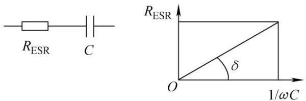
Figure 1-18 The relationship between the simplified equivalent circuit of an electrolytic capacitor and the loss tangent
Since the test standard for capacitor loss factor uses a frequency of 60Hz, the test frequency for capacitor loss factor is 120Hz, the lowest ripple frequency after 60Hz AC full wave or bridge rectification (2 times 60Hz). The test value under this test condition is 20% larger than the loss factor under my country’s 50Hz power grid frequency.
The loss factor measurement is performed at 25°C/120Hz, with no forward voltage bias, and a signal voltage with a maximum AC effective value of 1V. The ESR calculated from the measured loss factor is the ESR of the capacitor at 120Hz.
It can be seen from the definition of loss factor, test methods and the explanation of Figure 1-18: The loss factor is the ratio of the ESR and capacitive reactance of the capacitor, and has nothing to do with dielectric loss.
8.2 Analysis of electrolytic capacitors-Relationship between dissipation factor and application of aluminum electrolytic capacitors
Ambient temperature and operating frequency have a significant impact on the dissipation factor of aluminum electrolytic capacitors. The relationship between the loss factor of aluminum electrolytic capacitors, temperature and frequency is shown in Figure 1-19.
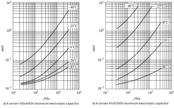
Figure 1-19 The relationship between the loss factor of aluminum electrolytic capacitors, temperature and frequenc
As can be seen from Figure 1-19, the dissipation factor of the aluminum electrolytic capacitor will decrease as the temperature rises. Therefore, the loss caused by the dissipation factor is suppressed as the temperature rises, which is a convergence result. Since the resistivity of the electrolyte decreases as the temperature increases, the dissipation factor increases as the measured temperature decreases (ESR increases).
The loss factor of aluminum electrolytic capacitors increases with frequency. As can be seen from Figure 1-19: as the frequency increases by one order of magnitude, the loss factor also increases by about an order of magnitude. This growth is basically consistent with the trend change of equation (1-4). It can also be seen from the figure that the actual loss factor increases faster than Equation (1-4). The reason is that the main cause of loss is the resistance of the electrolyte as the negative electrode, and the electrolyte is ion conductive, and ion conductivity is The losses generated at different frequencies are different. Therefore, in addition to the ESR loss, the loss of the aluminum electrolytic capacitor also includes the loss caused by the electrolyte under different frequencies.
The result of this increase in loss factor with frequency is qualitatively different from the loss factor of non-polar capacitors due to dielectric loss, because the dielectric (aluminum oxide) loss characteristics of aluminum electrolytic capacitors will never be this bad.Note: This article mainly talks about the Analysis of electrolytic capacitors-loss factor
This is the Analysis of electrolytic capacitors – loss factor
9. Analysis of electrolytic capacitors–leakage current
9.1 Analysis of electrolytic capacitors-Causes of leakage current and necessity of reduction
Causes of leakage current: The alumina dielectric is damaged during the cutting and riveting process of aluminum foil. After aging and repair, the performance is not as good as that of the single oxide film formed by the formation process, which will produce leakage current; the aluminum oxide film is corroded by chlorine ions in the electrolyte and causes defects. , thereby producing leakage current; the purity of the positive electrode foil (aluminum foil) cannot be 100%, and there will be trace amounts of other elements, which will produce a galvanic cell effect with the electrolyte and aluminum oxide film, destroy the aluminum oxide film, and produce leakage current.
It needs to be repaired by applying a DC voltage (anodization), so even if a DC voltage has been applied for a long time, a small repair current will still flow. This current is called leakage current.
Low leakage current means that there are very few chloride ions in the electrolyte, which can lead to good repair results. It also indicates that the aluminum oxide dielectric used as an insulating layer is good. The iron and copper ions in the electrolyte and aluminum foil will produce galvanic cell effect current after applying voltage to the electrodes of the aluminum electrolytic capacitor, which requires more charge to consume it. This is why some aluminum electrolytic capacitors require more charge after the first power-up. The reason why it takes a long time for the “leakage current” to drop to the normal value. This phenomenon also illustrates the necessity for aluminum electrolytic capacitors to be aged before leaving the factory.
9.2 Analysis of electrolytic capacitors-Measurement method of leakage current
The test method and test conditions for the leakage current of aluminum electrolytic capacitors are: at 25°C, the capacitor under test is connected in series with a 1000Ω protection resistor, and is directly connected to the rated voltage to measure the leakage current. After applying voltage for 5 minutes, the leakage current does not exceed the maximum value in the instruction manual. Small-capacity aluminum electrolytic capacitors can use the 1-min test results, while large-capacity aluminum electrolytic capacitors will require longer test times. Figure 1-20 shows the relationship between leakage current and charging time when an aluminum electrolytic capacitor is connected to a series resistor followed by a DC voltage.
It can be seen from the characteristic curve that the current will infinitely approach the final leakage current value – the current value required to repair the alumina dielectric.
The leakage current of aluminum electrolytic capacitors can be calculated. For example, the Ilkop of EPCOS aluminum electrolytic capacitors is
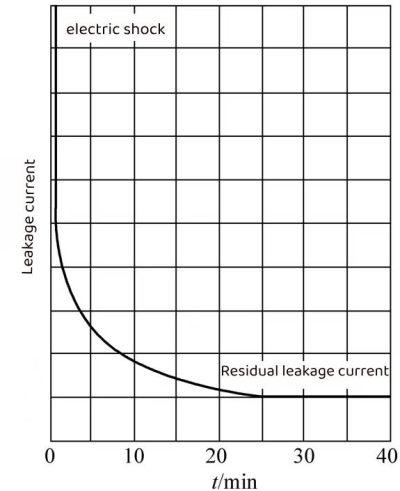
Figure 1-20 Relationship between leakage current and charging time of aluminum electrolytic capacitors
LL level
Ilkop=0.0005CrUr+1
GP level
Ilkop=0.001CrUr+3
In the formula, Ilkop, Cr, and Ur are the operating leakage current (μA), rated capacitance (μF), and rated voltage (V) respectively.
This result is obtained at rated voltage Ur at 20°C.
9.3 Analysis of electrolytic capacitors-Relationship between leakage current and application environment
Leakage current is one of the biggest problems that damages aluminum electrolytic capacitors, because leakage current will consume the electrolyte, causing the aluminum electrolytic capacitor to dry out prematurely and fail. Therefore, special attention should be paid to leakage current issues.
9.3.1 Long-term storage will increase the leakage current of aluminum electrolytic capacitors and its solution. It should be noted that aluminum electrolytic capacitors have no application after being stored in a voltage-free state for a long time. The chloride ions in the electrolyte cause the greatest damage to the aluminum oxide film, especially when stored at very high temperatures. In this case, no leakage current flows from the oxide layer to the anode, and the oxide layer cannot be regenerated. When the voltage is connected after extended storage, a higher than normal leakage current will be generated. However, as the oxide layer regenerates during use, the leakage current will gradually decrease to normal values. At the same time, due to the gradual recovery of the galvanic cell effect of iron and copper ions, the leakage current of the aluminum electrolytic capacitor will require a long period of voltage application to recover. This process is called aging or empowerment. Aluminum electrolytic capacitors are usually energized before use.
Aluminum electrolytic capacitors can be stored in a voltage-free state. If they are stored by domestic general manufacturers for 1 year or by well-known domestic and foreign manufacturers for more than 2 years, they need to be empowered before application.
If the aluminum electrolytic capacitor that has been placed for a long time has not been energized, the leakage current value may be as high as 100 times its normal value when it is first powered on! Can the capacitor withstand this high initial leakage current when the capacitor is stored for more than 2 years? Therefore, it is best to energize the aluminum electrolytic capacitor before installing it into the circuit. In addition, when the circuit with a capacitor has reached or exceeded the storage life, the capacitor should be operated in a no-load state for 1 hour to prevent excessive leakage current and ripple current from overheating the aluminum electrolytic capacitor and causing explosion. It can be seen that circuits with aluminum electrolytic capacitors should be powered on once a year (for several hours) during storage to ensure the performance of the aluminum electrolytic capacitors in the circuit during storage.
It is undeniable that well-sealed aluminum electrolytic capacitors can even be stored for 15 years without any performance loss. If the storage time of aluminum electrolytic capacitors does not exceed the limit time, the capacitors can be directly applied to the rated voltage after being taken out of the library. In this case, the enabling process may not be needed.
It should be noted that if an expired electrolytic capacitor is stored, even if the leakage current at room temperature is reduced to the factory value through normal temperature energization, the service life of the electrolytic capacitor cannot be guaranteed, and the bottom of the electrolytic capacitor may even bulge when re-aging at high temperature. Such electrolytic capacitors cannot be provided to customers as normal products.
Likewise, if electrolytic capacitors are left on the client side for too long, their lifespan will be shortened.
9.3.2 Voltage characteristics of leakage current In the data sheet, the leakage current test conditions of aluminum electrolytic capacitors are: voltage is the rated voltage, and temperature is the maximum operating temperature. Under different voltages, the leakage current of aluminum electrolytic capacitors changes with the applied voltage, as shown in Figure 1-21.
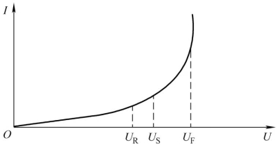
Figure 4-21 The relationship between leakage current and voltage of aluminum electrolytic capacitors
In Figure 1-21, UR is the rated voltage of the aluminum electrolytic capacitor, US is the surge voltage, and UF is the anodization voltage (breakdown voltage). It can be seen from the figure that UF>US>UR, the leakage current increases as the terminal voltage of the electrolytic capacitor rises. When the terminal voltage exceeds the rated voltage and approaches the surge voltage, the rising rate of the leakage current increases with the rise of the voltage. When the terminal voltage rises, When the voltage is close to the breakdown voltage, the leakage current will increase sharply, and finally become a constant voltage characteristic similar to avalanche breakdown. This “avalanche breakdown” characteristic is reversible when the aluminum electrolytic capacitor does not cause irreversible damage such as explosion or convex bottom. of. The actual rated voltage of an aluminum electrolytic capacitor can be measured by the characteristic that the leakage current of the aluminum electrolytic capacitor increases significantly after the capacitor terminal voltage approaches the surge voltage.
Figure 1-22 shows the relationship between the leakage current and the applied voltage of the 4700μF/450V/85℃ aluminum electrolytic capacitor produced by CDE Company.
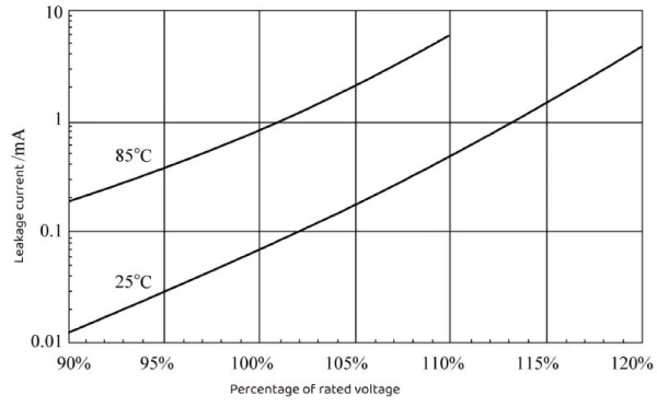
Figure 1-22 Relationship between leakage current and applied voltage
As can be seen from Figure 1-22: At the maximum operating temperature of 85°C, the leakage current at 100% rated voltage is 4 times the leakage current at 90% rated voltage, and twice the leakage current at 95% rated voltage. Obviously, reducing the operating voltage of aluminum electrolytic capacitors will help reduce leakage current. It can also be seen from the figure that while maintaining the same leakage current, lowering the operating temperature can increase the operating voltage. Taking the leakage current as 1mA as an example, when the ambient temperature is 85°C, the corresponding working voltage is 101.5% of the rated voltage. When the ambient temperature drops to 25°C, the corresponding working voltage is 113% of the rated voltage.
It can be seen that under the maximum operating temperature and rated voltage conditions, the heat generated by the aluminum electrolytic capacitor will increase the additional temperature rise of the core package of the aluminum electrolytic capacitor by 1 to 1.5°C, accounting for approximately 10% to 20% of the total temperature rise.
9.3.3 Temperature characteristics of leakage current From a qualitative relationship, taking an aluminum electrolytic capacitor with a maximum operating temperature of 85°C as an example, the change trend of leakage current and temperature is shown in Figure 1-23. It can be seen that the leakage of the aluminum electrolytic capacitor The current increases significantly as the temperature rises.
From a quantitative relationship point of view, the relationship between leakage current and temperature of the 4700μF/450V/85℃ aluminum electrolytic capacitor produced by CDE is shown in Figure 1-24.
As can be seen from Figure 1-24: the leakage current at 85°C is 14 times that of room temperature (25°C). The reduction of leakage current can effectively reduce the consumption of electrolyte and help extend the service life of aluminum electrolytic capacitors.
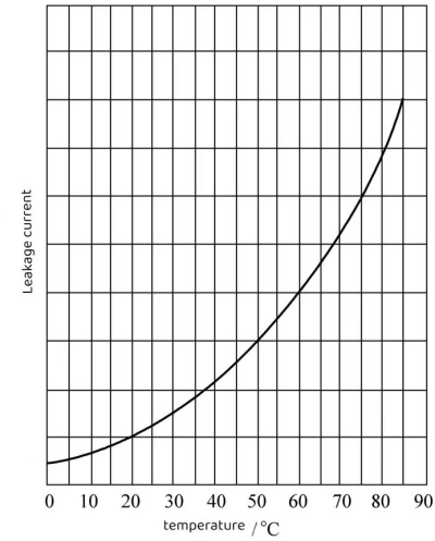
Figure 1-23 Relationship between leakage current and temperature of aluminum electrolytic capacitors
9.3.4 Leakage current loss As can be seen from Figure 1-22 and Figure 1-24, at the highest operating temperature, the leakage current loss of the aluminum electrolytic capacitor at the rated voltage UR is about 0.4W, while operating at room temperature is only 0.4W. 0.03W. If the operating voltage is reduced to 90% UR, the loss can be reduced to 0.004W. From the above analysis, it can be seen that appropriately reducing the operating voltage and ambient temperature can reduce the leakage current by one to two orders of magnitude, which is beneficial to the long-term reliable use of aluminum electrolytic capacitors.
Therefore, from the perspective of leakage current, it is best to regularly energize aluminum electrolytic capacitors regardless of whether they are used to ensure the performance of aluminum electrolytic capacitors; aluminum electrolytic capacitors are not suitable for high-temperature environments, both for storage and operation. High-temperature environments will greatly shorten the life of aluminum electrolytic capacitors. The life of electrolytic capacitors and the leakage current performance of aluminum electrolytic capacitors are reduced.
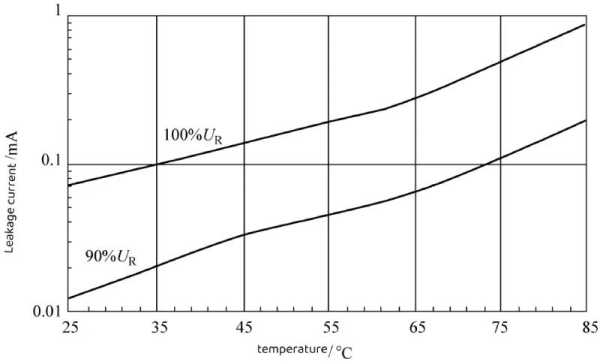
Figure 1-24 Relationship between leakage current and temperature
This is the Analysis of electrolytic capacitor — leakage current
10. Analysis of electrolytic capacitors–operating temperature range
10. 1 Analysis of electrolytic capacitors-Operating temperature of electrolytic capacitors
Since the electrolyte of the aluminum electrolytic capacitor is the negative electrode, the increase in temperature will cause the electrolyte to reach the boiling point. Therefore, the boiling point of the electrolyte will be the insurmountable maximum operating temperature of the aluminum electrolytic capacitor. In practical applications, the maximum operating temperature is 10 to 20°C lower than the boiling point of the electrolyte; similarly, because the negative electrode of the aluminum electrolytic capacitor is the electrolyte, when the temperature is too low, the electrolyte will become viscous or even solidify, resulting in aluminum Electrolytic capacitors cannot be used. Therefore, aluminum electrolytic capacitors also have lower limits for operating and storage temperatures. The entire temperature range between the upper and lower operating temperature limits is the operating temperature range of the aluminum electrolytic capacitor.
For lower-level commercial applications, the maximum and minimum operating/storage temperatures of aluminum electrolytic capacitors are 85°C and -20°C, respectively. If there are special requirements for low temperature, the minimum operating temperature can reach -40℃; if the working/storage temperature is relatively high, an aluminum electrolytic capacitor with a maximum working/storage temperature of 105℃ is required; when encountering a higher temperature working environment, For example, when used in energy-saving lamps/LEDs or in automobile engine compartments, the maximum operating temperature of aluminum electrolytic capacitors is required to reach 125°C or even 150°C.
From the above analysis, it can be seen that the maximum operating temperature of aluminum electrolytic capacitors can be divided into: 85°C for general applications, 105°C for higher operating temperatures, and 125°C or even 140°C or 150°C for very high operating temperatures.
10.2 Analysis of electrolytic capacitors-Usable time
Also because the negative electrode of the aluminum electrolytic capacitor is an electrolyte, the electrolyte will gradually dry up over time. When the electrolyte dries up to a certain extent, the actual effective area of the negative plate of the aluminum electrolytic capacitor will become significantly smaller, and the capacitance will decrease. began to decrease significantly, accompanied by a significant increase in ESR. When the capacitance decreases and the ESR rises to a certain level, the aluminum electrolytic capacitor will lose its application significance, which marks the end of the life of the aluminum electrolytic capacitor.
Depending on the compromise between application environment and cost, aluminum electrolytic capacitors of different specifications have different lifespans.
10.3 Analysis of electrolytic capacitors-Rated temperature and life rating parameters of aluminum electrolytic capacitors
To sum up, the rated temperature of aluminum electrolytic capacitors is the maximum temperature allowed for operation and storage. According to the working environment temperature requirements, it can usually be divided into five temperature levels: 85°C, 105°C, 125°C, 140°C and 150°C. There are different lifespans under each temperature level, such as 1000h, 2000h, 3000h, 4000h, 5000h, 8000h, 10000h or even higher.
This is the Analysis of electrolytic capacitors–operating temperature range
11.Analysis of electrolytic capacitors-lifespan
Lifetime is an important parameter for electrolytic capacitors. The life of an electrolytic capacitor is generally defined as the life value under the condition that the superimposed amplitude of DC voltage and AC voltage applied at the highest operating temperature does not exceed the rated voltage, and the ripple current flowing through the electrolytic capacitor is the rated ripple current. The capacitance, leakage current, and dissipation factor of the electrolytic capacitor after life testing should not exceed the limit values specified in the data sheet.
The actual life of an electrolytic capacitor becomes longer as the operating temperature of the electrolytic capacitor decreases. It is generally believed that for every 10°C decrease, the life span doubles; some electrolytic capacitor manufacturers also state that for every 7°C decrease, the life span doubles; some electrolytic capacitor manufacturers It is given that for every 5°C lowering, the lifespan doubles. Therefore, the life conversion of electrolytic capacitors below the maximum operating temperature needs to be converted based on the life curve given by each manufacturer and its specific specifications. There is usually no universal conversion formula.
The long or short life of an electrolytic capacitor is related to the size of the electrolytic capacitor core and the amount of electrolyte impregnated with it. For example, the life of a lead-pin electrolytic capacitor with a diameter of 12.5mm or more can reach 10,000 hours, while an electrolytic capacitor with a diameter of 10mm made of the same material and the same process can only have a life of 8,000 hours. Similarly, those with a diameter of less than 8mm can only achieve 5000h. The same applies to electrolytic capacitors with other lifespans.
There are two electrolytic capacitor life parameters in the electrolytic capacitor data sheet, one is the high temperature load life and the other is the high temperature static life.
High temperature load life is the most commonly used electrolytic capacitor life parameter. The test conditions are: rated ripple current is applied at the highest ambient temperature and does not exceed the rated voltage. With continuous loading, the capacitance change is less than ±20% of the initial capacitance, the loss factor is not greater than 200% of the initial value, and the leakage current is not higher than the specified value. The duration of this loading is the high-temperature load life of the electrolytic capacitor.
High temperature load life is the life under the highest ambient temperature and loaded with rated ripple current. If no ripple current is loaded and only DC voltage is loaded, the life will be longer than the high temperature load life, which is generally 150% to 200% of the high temperature load life. .
High temperature load life also reflects the relative life span of electrolytic capacitors when used.
The criteria for high-temperature static life are: when the ambient temperature is 85°C and the loading voltage is zero, after being left for 1000 hours, the capacitance change is less than ±20% of the initial capacitance, the loss factor is not greater than 200% of the initial value, and the leakage current is less than higher than the specified value.
The high temperature static life reflects the decay rate of the performance of the electrolytic capacitor when it has no oxide film repair ability at the highest ambient temperature. This decay is mainly due to the high-temperature erosion of the aluminum oxide film by the electrolyte and the degree of hydration reaction, which reflects the reliability and durability of the electrolytic capacitor.
Factors such as ripple current parameters and ripple current frequency characteristics also affect the life of electrolytic capacitors. Therefore, the life of electrolytic capacitors needs to be considered under the influence of various parameters.
This is the Analysis of electrolytic capacitors– lifespan
Conclusion
Analysis of electrolytic capacitors – mainly describes the classification, definition, shape, labeling method, parameter identification, voltage parameters, capacitance, loss factor, leakage current, operating temperature range, lifespan, etc. of electrolytic capacitors.To learn more about electrolytic capacitors, please click https://capacitorsfilm.com