1 Failure modes and factors failure of aluminum electrolytic capacitors
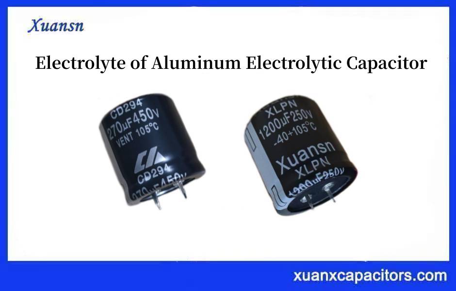
The positive and negative lead-out electrodes and shells of aluminum electrolytic capacitors are made of high-purity aluminum. The medium of aluminum electrolytic capacitors is an aluminum oxide film formed on the surface of the positive electrode. The real negative electrode is the electrolyte, which is equivalent to an electrolytic cell when working, except that The anodized layer on the surface of the positive electrode has been formed, no electrochemical reaction occurs, and the current is theoretically zero. Due to the presence of impurities in the electrode and electrolyte, a small leakage current will be caused. From the perspective of phenomena, the common failure phenomena and failure modes of aluminum electrolytic capacitors include electrolyte drying up, pressure release device action, short circuit, open circuit (no capacitance), excessive leakage current, etc. Therefore, the factors that cause the failure of aluminum electrolytic capacitors can be divided into two parts: the characteristics of aluminum electrolytic capacitors and the application environment of aluminum electrolytic capacitors.
2 Characteristics of aluminum electrolytic capacitors
These include the selection and formula of manufacturing materials (electrode, electrolyte, sealing, etc.), manufacturing process, and technology (sealing method, heat dissipation technology, etc.).
2.1 Manufacturing materials
In a pure capacitor, no electrochemical reaction should occur, which is the essential difference between a capacitor and a battery. The electrochemical reaction in the battery can output or store electrical energy, while the electrochemical reaction not in the capacitor will store out electrical energy, but will also damage or even damage the capacitor.
Due to the presence of electrolytes in the aluminum electrolyte capacitor, once there are impurities in the electrode material, the primary battery effect will be formed, causing excessive leakage current and corrosion of the aluminum electrode. be high-purity aluminum, and it cannot be doped with any other impurities during the manufacturing process of aluminum electrolyte capacitors.
Since the medium of aluminum electrolyte capacitors is aluminum, once chloride ions exist in the electrolyte, the chloride ions will replace the oxygen ions in the aluminum and become aluminum chloride and dissolve in the electrolyte, thereby destroying the aluminum medium and causing an increase in leakage current to the extent that it cannot be used, it may even cause a short circuit.
In addition to electrode materials and electrolytes, sealing materials are also one of the keys to eliminating premature failure of aluminum electrolyte capacitors. If the sealing materials do not match, liquid leakage will occur, causing a period to aluminum electrolyte fail capacitors.
Strict material quality control can prevent early failure problems caused by manufacturing materials.
2.2 Manufacturing Process and technical aspects
In terms of the manufacturing process, the cutting of the electrode sheet, the riveting of the lead wire, the winding of the core package, the immersion or filling of the electrolyte, and the sealing process are not done well, which may cause the performance of the aluminum electrolytic capacitor to decline or fail.
In the process of cutting the electrode sheet and riveting the lead wire, it will cause certain damage to the aluminum oxide dielectric film. If the damage is too large, it cannot be repaired even through aging in time, resulting in early failure of excessive leakage current or breakdown short circuit; electrolysis Insufficient liquid entry or insufficient filling may cause the failure of aluminum electrolytic capacitors with insufficient capacitance or insufficient life; poor sealing of the aluminum electrolytic capacitor will cause the electrolyte to dry up prematurely and cause failure with insufficient life.
If the aluminum electrolytic capacitor is placed for some time and white salt stains or oil-like electrolytes appear near the lead wire or the seal, it means that the electrolyte has leaked due to poor sealing, and this type of electrolytic capacitor cannot be used.
Only when the above-mentioned manufacturing problems are all solved, the aluminum electrolytic capacitors shipped are qualified, and the early failure problems caused by manufacturing problems can be avoided.
3 Influence of application environment on the failure of aluminum electrolytic capacitors
If there is no problem with the quality of the electrolytic capacitor, the failure problem is in the application environment. The design and application environment of aluminum electrolytic capacitors mainly includes ambient temperature, heat dissipation method, voltage, and current parameters. For capacitor users, short circuits and open circuits are “catastrophic failures”, or “fatal failures”, which completely lose the function of capacitors. The other types of failure modes (that is, the failure caused by the second type of factors) are generally classified as “deterioration failure” or “depletion failure”.
The analysis of the influence of the application environment on the failure of aluminum electrolytic capacitors is as follows: the failure of aluminum electrolytic capacitors can be divided into overvoltage failure, exhaustion failure, open circuit, short circuit, pressure release device action, etc.
3.1 Overvoltage failure
In the application of aluminum electrolytic capacitors, various overvoltages may lead to failure modes such as performance degradation and breakdown.
The main cause of overvoltage is instantaneous overvoltage or surge voltage. If the rated voltage of the aluminum electrolytic capacitor is improperly selected (for example, the possible overvoltage is not considered) or the power supply environment is harsh, the overvoltage failure of aluminum electrolytic capacitors may occur.
3.2 Depletion failure
The so-called depletion failure is when the performance of aluminum electrolytic capacitors deteriorates due to the gradual drying of the electrolyte during use. Usually, the deterioration failure of aluminum electrolytic capacitors is generally defined as the end of life caused by the decline of one of the four key parameters of capacitance C, leakage current (IL), loss tangent (tan δ), and ESR increase beyond a certain range.
(1) The capacity decreases and the loss increases. Usually, the end of life of an electrolytic capacitor is judged based on the capacitance falling below 80% of the rated (initial value),lead to the failure of aluminum electrolytic capacitors. Due to the filling of electrolyte electrolytes in early aluminum electrolytic capacitors, the capacitance of aluminum electrolytic capacitors decreases slowly in the early stage of operation. The electrolyte gradually decreases as the working electrolyte continuously repairs the anodic oxide film damaged by impurities during the load process. In the later stage of use, due to the decrease of the electrolyte volatilization, it is difficult for the electrolyte with increased viscosity to fully contact the oxide film layer on the surface of the corroded rough aluminum foil, so that the effective area of the plate of the aluminum electrolytic capacitor begins to decrease rapidly. Small, that is, the capacity of the anode and cathode foils decreases rapidly, causing a sharp drop in capacitance. Therefore, it can be considered that the capacity reduction of the aluminum electrolytic capacitor is caused by the volatilization of the electrolyte,then lead to the failure of aluminum electrolytic capacitors. The most important reason for the volatilization of the electrolyte is the high-temperature environment or heat. The usually high-temperature environment is better understood.
The reason why the aluminum electrolytic capacitor heats up due to the application conditions is that the ripple (or pulsation) current flows through the aluminum electrolytic capacitor when it is working in rectification and filtering (including high-frequency rectification and filtering of switching power supply output) and power supply bypass of the power circuit. For electrolytic capacitors, the ESR of aluminum electrolytic capacitors generates losses and converts them into heat to generate heat.
When the electrolyte of an aluminum electrolytic capacitor evaporates more and the solution becomes thicker, the resistivity increases due to the increase of viscosity, which increases the equivalent series resistance of the working electrolyte, resulting in a significant increase in capacitor loss and loss angle,lead to the failure of aluminum electrolytic capacitors. For example, for an electrolytic capacitor with a working temperature of 105C, when the maximum core package temperature is higher than 125C, the viscosity of the electrolyte will increase sharply, and the ESR of the electrolyte will increase by nearly ten times. The increased equivalent series resistance will generate more heat, resulting in Faster volatilization of electrolyte. Such a cycle goes on and on, and the capacity of the aluminum electrolytic capacitor drops sharply, and may even cause an explosion.
In addition, if the viscosity of the working electrolyte increases too much at low temperatures, it will also cause increased loss and a sharp drop in capacitance. The low-temperature performance of the boric acid-ethylene glycol system working electrolyte is not good, and the viscosity is too high, resulting in a sharp increase in equivalent series resistance, increased loss, and reduced effective capacitance, which will cause aluminum electrolytic capacitors to fail when used in severe cold environments.
(2) Leakage current rises. Increased leakage current often causes aluminum electrolytic capacitors to fail.
The main reasons for excessive leakage current are: low level of empowerment process, insufficient density and firmness of the formed oxide film, backward chip opening process, serious damage and contamination of the oxide film, poor working electrolyte formula, low purity of raw materials, The chemical and electrochemical properties of the electrolyte are difficult to stabilize for a long time, the purity of the aluminum foil is not high, and the content of impurities is high.
Among them, the oxide film damage and serious contamination are the main reasons for the increased increasing leakage current. The flaws and defects of the oxide film itself, as well as the impurities such as chloride ions and sulfate ions in the electrolyte, damage the characteristics of the oxide film. Under the rated conditions, the oxygen generated by the electrolysis inside the aluminum electrolytic capacitor will repair the oxide film, that is, aluminum electrolysis The self-healing function of electrical appliances.
However, when the external positive voltage is increased to exceed the rated voltage (this situation is common in the circuit), the negative polar acid ions such as chloride ions and sulfate ions will accelerate the movement under the action of a strong electric field and dioxide Aluminum reacts, causing oxide film damage and serious contamination. At this time, the oxygen generated by the electrolyte in the aluminum electrolytic capacitor is not enough to completely repair the oxide film, increasing leakage current. The leakage current causes the oxide film on the contaminated part to decompose, resulting in a perforation. causing the current to increase further.
The impurity content of the aluminum foil is relatively high, and the size of the iron impurity particles is generally larger than the thickness of the anodized film, which makes the current easy to conduct. The existence of copper and silicon impurities affects the transformation of aluminum oxide to the crystalline structure, and copper and aluminum can also form micro-batteries in the electrolyte, which causes the aluminum foil to be corroded and damaged. In short, the presence of metal impurities in aluminum foil will increase the leakage current of aluminum electrolytic capacitors.
With the increase in use and storage time, the solution in the electrolyte is gradually consumed and volatilized, which increases the acid value of the solution and corrodes the oxide layer during storage. At the same time, due to the aging and dryness of the electrolyte, oxygen ions cannot be provided to repair the oxide film under the action of the electric field, thus losing the self-healing effect, the oxide film is damaged, and the leakage current increases.
If the anodic oxide film formed during the energization process is not dense and firm enough, the oxide film will be severely damaged in the subsequent cutting and riveting process. This kind of anodic oxide film is difficult to repair and perfect in the final aging process so during the use of the capacitor, local self-healing cannot repair the oxidation barrier, resulting in a large leakage current.
If the leakage current is too large, it will cause fatal failures such as the action and breakdown of the pressure release device (explosion-proof valve) of the aluminum electrolytic capacitor:
① When the leakage current is large, the rate of gas generated by electrolysis is faster, and the consumed electrolyte is used to repair the anodic oxide film, and the generated gas is stored in the capacitor shell. The longer the working time, the greater the leakage current, the more gas in the shell, and the higher the temperature. The air pressure difference inside and outside the metal shell of the capacitor will increase with the increase of the working voltage and working time. If the product is not well sealed, it will cause liquid leakage; if the seal is good, and there are no explosion-proof measures, the capacitor will explode when the air pressure increases to a certain extent. High-voltage large-capacity capacitors have a large leakage current and are more likely to explode.
② If the leakage current is too large, the insulation effect of the oxide film will be damaged, and the direct contact between the cathode and the anode will cause a short circuit breakdown. For example, when the riveting process is not good, the burrs on the lead-out chaff will seriously puncture the oxide film, the leakage current at the punctured part will be large, and the local overheating will cause thermal breakdown of the capacitor.
3.3 Causes of open circuits
Aluminum electrolytic capacitors may fail in an open circuit when they work in a high temperature or hot flash environment for a long time. The reason is that the anode lead-out foil is broken due to electrochemical corrosion. For high-voltage large-capacity capacitors, this failure mode is more common. In addition, if the anode lead-out foil and the anode foil are riveted, if they are not fully leveled, it will cause poor contact and intermittent open circuit of the capacitor.
When the working electrolyte with DMF (dimethylamine) as the solvent is used in the aluminum electrolytic capacitor, the DMF solution is an oxidizing agent, and its oxidation ability is stronger at high temperatures. After working for some time, the capacitor may be opened due to the oxide film formed on the riveting part of the anode lead-out foil and the welding piece. If an ultrasonic welding machine is used to connect the lead-out foil and the solder joint, this type of failure can be reduced.
4 Action of the pressure relief device
The electrolyte in the aluminum electrolytic capacitor is caused by the gas generated by internal high-temperature boiling or the gas generated by the electrochemical process, which causes the internal high pressure to cause the explosion of the electrolytic capacitor. To eliminate the explosion of aluminum electrolytic capacitors, aluminum electrolytic capacitors with a diameter of more than 8mm are equipped with pressure-release devices. These pressure-release devices operate before the air pressure inside the electrolytic capacitor reaches the dangerous pressure that has not yet caused the aluminum electrolytic capacitor to explode, and release the gas. With the action of the pressure relief device, the aluminum electrolytic capacitor is declared invalid. (1) The electrochemical process causes the pressure relief device to operate. The leakage current of aluminum electrolytic capacitors is a violent electrochemical process, which has been discussed in detail before and will not be repeated. The electrochemical process will generate gas, and the accumulation of these gases will cause the internal pressure of the aluminum electrolytic capacitor to rise, and finally reach the pressure release device to release the pressure,lead to the failure of aluminum electrolytic capacitors.
(2) Excessive temperature causes the pressure release device to operate. If the temperature of the aluminum electrolytic capacitor is too high, it may be that the ambient temperature is too high. For example, there are heating elements near the aluminum electrolytic capacitor or the entire electronic device is in a high-temperature environment.
The second reason why the aluminum electrolytic capacitor temperature is too high is that the core package temperature is too high. The root cause of excessive core package temperature is excessive ripple current flowing through aluminum electrolytic capacitors. Excessive ripple current produces an excessive loss in the ESR of the aluminum electrolytic capacitor and generates excessive heat, causing the electrolyte to boil to generate a large amount of gas, causing the internal pressure of the aluminum electrolytic capacitor and the pressure release device to operate when it rises sharply,lead to the failure of aluminum electrolytic capacitors.
(3) Action of the pressure release device caused by low ambient air pressure. If the aluminum electrolytic capacitor works in an application environment where the air pressure is too low such as high altitude or high altitude, the pressure release device will act prematurely, causing the aluminum electrolytic capacitor to fail prematurely. This is the limitation of the aluminum electrolytic capacitor to the application environment
5 Special failure modes
In high-voltage aluminum electrolytic capacitors, a special failure mode often occurs: burning. Aluminum electrolytic capacitors can cause both primary combustion and secondary combustion.
5.1 Combustion of Aluminum Electrolytic Capacitors
(1) Primary combustion mode. Primary combustion means that the electrolytic capacitor burns itself under certain conditions, which is the so-called “active combustion”.
In the formation of the fire source, the electrostatic energy accumulated in the capacitor can be connected to the spark discharge through the arc between the electrodes under certain conditions, and this spark is the “fire source”. The electrostatic energy gain is W=1/2CV2, where C is the electrostatic capacity and V is the charging voltage, which is proportional to the square of the charging voltage, so high voltage will greatly increase the amount of static electricity accumulated on the capacitor electrodes. Generally speaking, aluminum electrolytic capacitors for power input are more likely to cause internal spark discharge due to their high operating voltage, which will directly cause the overflowing electrolyte to burn. The working voltage of the aluminum electrolytic capacitor used for power output is relatively low, and it usually does not reach the electrostatic energy required for internal spark discharge, so primary combustion rarely occurs.
Combustible substances that can be burned: due to the presence of combustible substances such as electrolyte, isolation liner and hydrogen gas around the fire source, it is easy to catch fire and burn.
Oxygen supply: Due to the impact of heat generation and arcing between electrodes, the internal pressure of the capacitor will rise sharply until the safety valve opens. At this time, the combustibles will be ignited and continue to burn when they come into contact with the outside air. The larger the opening area of the safety valve, the more oxygen will be supplied and the more intense the combustion will be. Conversely, the opening area is so small that the combustibles cannot fly out to contact with the outside air, and the combustion will not continue at this time, and at most there will be a little burnt trace in the arcing part.
(2) Mode of secondary combustion. Secondary combustion means that the aluminum electrolytic capacitor is ignited by an external fire source, or the electrolyte is sprayed to a nearby high-energy area, causing a short circuit, arcing, and then a fire, lead to the failure of aluminum electrolytic capacitors,which is the so-called passive flammability.
Leakage or overflow of electrolyte: When the airtightness of the seal is poor or the safety valve is opened, the electrolyte will leak or overflow from the inside of the capacitor and circulate to the high-energy area (such as the high-energy part on the circuit board) , cause short circuit, flashover, cause the electrolyte to catch fire and then trigger the combustion of combustibles other than the electrolyte,lead to the failure of aluminum electrolytic capacitors.
External fire source: The combustible material around the capacitor burns to become a fire source. When the capacitor sealing material catches fire or the capacitor is heated by an external heat source and the safety valve opens, the electrolyte leaks and is ignited,lead to the failure of aluminum electrolytic capacitors.
(3) Instantaneous overheating. As mentioned earlier, usually the core temperature of aluminum electrolytic capacitors is reduced by 10C, and its life will be doubled. This core is located roughly in the center of the capacitor and is the hottest point inside the capacitor. However, when the capacitor heats up close to its maximum allowable temperature, for most types of capacitors, at 125C, the electrolyte will be squeezed out by the capacitor core package, causing the ESR of the capacitor to increase to 10 times the original. Under this effect, instantaneous over-temperature or over-current can permanently increase ESR, lead to the failure of aluminum electrolytic capacitors. In the application of high temperature and large ripple current, special attention should be paid to the possibility of instantaneous overtemperature, and special attention should be paid to the cooling of electrolytic capacitors.
6 Prevention of Failure of Aluminum Electrolytic Capacitors
6.1 Prevention of overvoltage failure of Aluminum Electrolytic Capacitors
Capacitors are easily broken down under overvoltage conditions,cause failure of aluminum electrolytic capacitors and instantaneous high voltages often appear in practical applications.
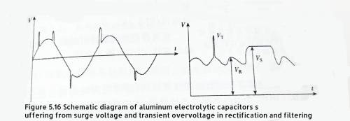
Figure 5.16 Schematic diagram of aluminum electrolytic capacitors suffering from surge voltage and transient overvoltage in rectification and filtering
In the figure, VR, VS, and .VT are rated voltage and surge voltage respectively. The transient high voltage test condition is 1000 cycles, 330s without load, 30s with load; VS is generally 110%~115% times VR.
It can be seen in the figure that due to the frequent transient overvoltage or surge voltage in the AC power grid, this transient overvoltage or surge voltage is transmitted to the electrolytic capacitor that completes the filtering function through the rectifier, resulting in overvoltage or transient overvoltage of the filter electrolytic capacitor ,cause failure of aluminum electrolytic capacitors.
The rectifier filter capacitor will cause instantaneous overvoltage or surge voltage of the filter capacitor due to the instantaneous overvoltage or surge voltage of the AC grid. Similar transient overvoltages or surge voltages also occur during power-up of circuits, especially in LC filters. For example, during the power-on process, because the filter inductor releases the stored energy into the filter capacitor, the filter capacitor will experience an instantaneous overvoltage,lead to the failure of aluminum electrolytic capacitors,as shown in Figure 5.17.
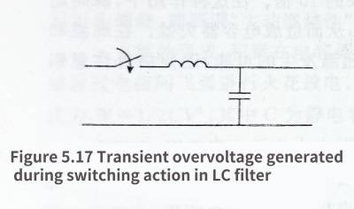
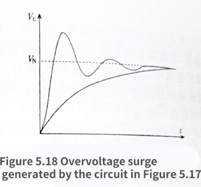
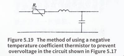
Figure 517 Transient overvoltage generated during switching action in LC filter
Figure 5.18 Figure 5.17 Overvoltage surge generated by the circuit
Figure 5.19 Using a negative source coefficient thermistor to prevent overvoltage in the circuit shown in Figure 5.17
This instantaneous overvoltage will produce “overshock” on the capacitor (Figure 5.18),cause failure of aluminum electrolytic capacitors. Soft switching techniques, which can employ NTC thermistors, are effective against transient overvoltages (Figure 5.19).
The filter before the rectifier can filter out some high-speed transient high voltage, but not all.
6.2 Prevention of reverse polarity
If the positive and negative terminals of the aluminum electrolytic capacitor are connected incorrectly, it will only take a short time to cause damage to the capacitor,lead to the failure of aluminum electrolytic capacitors. Therefore, in order to avoid similar connection errors, the direction of the positive terminal of the capacitor will be rotated 90°, that is, the direction perpendicular to the axis of the two bolt terminals is the positive pole, and the direction along the axis of the two bolt terminals is the negative pole.
6.3 Protection against overheating
The current exceeding the rated value will cause the internal temperature of the capacitor to rise too high, and shorten its working life,lead to the failure of aluminum electrolytic capacitors.However, if the duration of the ripple current is short compared to the heat conduction time constant, it will generally not cause damage to the capacitor.
(1) Infer whether it is overheated by measuring the temperature of the aluminum electrolytic capacitor shell. The temperature of the core package inside the capacitor determines the working life of the aluminum electrolytic capacitor. A temperature sensor can be used to measure the internal temperature rise of the aluminum electrolytic capacitor during operation (the temperature sensor must directly contact the aluminum shell of the aluminum electrolytic capacitor).

Figure 5.20 Rules for preventing wrong polarity connection when aluminum electrolytic capacitors are placed horizontally
(2) Place the temperature sensor inside the core package of the aluminum electrolytic capacitor to detect whether it is overheated. For aluminum electrolytic capacitors connected by bolt ends, it can be measured by inserting a thermocouple inside the capacitor. In engineering practice, Figure 5.21 is relatively easy to implement, while Figure 5.22 can only be used in aluminum electrolytic capacitor product testing. The reason is that it is impossible for aluminum electrolytic capacitors connected by bolts to reserve a cavity for inserting a thermocouple in the sealed end cover or shell for measuring the temperature of the core package.
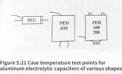

Figure 5.21 Temperature test points for aluminum electrolytic capacitors with various shapes
Figure 5.22 Test the temperature of the core package of an aluminum electrolytic capacitor with a bolted end connection by inserting a thermocouple inside the capacitor
(3) Estimation of core pack temperature under intermittent load. Aluminum electrolytic capacitors do not always work under continuous load conditions. For intermittent load conditions, the equivalent circuit of heat conduction shown in Figure 5.23 can be used for calculation.
In the figure, Rthhc is the thermal resistance from the aluminum electrolytic capacitor core package to the shell, Rthca is the thermal resistance from the aluminum electrolytic capacitor shell to the surrounding environment, Ch is the heat capacity of the aluminum electrolytic capacitor, and Cc is the heat capacity of the aluminum electrolytic capacitor shell.
The heat transfer parameters and ESR data for this example are available on the RIFA website.
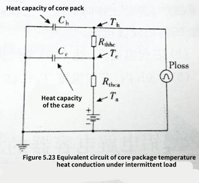
Figure 5.23 Equivalent circuit of core package temperature heat conduction at intermittent load
For example, if PEG126KL427BM type aluminum electrolytic capacitor (40V/2700uF) is selected, the thermal resistance from the core package to the shell is 7.7°C/W, and the thermal resistance from the shell to the environment is 18°C/W. Natural cooling does not use forced air cooling) , The heat capacity of the core package is 21J/℃, and the heat capacity of the shell is 2.5J/℃.
Find the ripple current.
Working state: 20A, 5kHz within 5min.
Closed state: no current within 15min.
Cycle: 20min.
Ambient temperature: 93°C., without forced air cooling.
ESR=8.7mΩ.
Power loss: I2rmsResr = 3.5W (“working” state).
Based on the given heat conduction parameters and the calculated power loss, the core package temperature (Th and case temperature (Tc) can be calculated by computer simulation, as shown in Figure 5.24
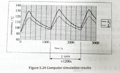
Figure 5.24 Computer simulation results
From the above analysis, we can see that the limit of intermittent work is as follows
(1) The intermittent operation mode with a duty cycle of 25% can increase the ripple current by 95% compared to the value during continuous operation.
(2) When the core package temperature Th reaches 135°C, the maximum ripple current can still be applied
(3) Within 100h, the core package temperature Th≦45℃, can work at the maximum ripple current