The manufacturing process of aluminum electrolytic capacitors is very rigorous and precise divided into the following steps:
If you disassemble the shell of an aluminum electrolyte capacitor, you will see that there are several layers of aluminum foil and several layers of electrolytic paper. The aluminum foil and the electrolytic paper are attached together and wound into a tubular organ, so that every two layers of aluminum foil In the middle is a layer of electrolytic paper that has absorbed electrolyte.
The essentials of aluminum foil in the manufacturing process of aluminum electrolytic capacitors. In order to increase the war area between the aluminum foil and the electrolyte, the appearance of the aluminum foil in the capacitor is not smooth, but its appearance is formed into a rugged shape by the electrochemical corrosion method, so that the appearance product can be increased by 7 to 8 times. The process of electrochemical decay is relatively complicated, which involves the type and concentration of the decay solution, the appearance of the aluminum foil, the rate of decay, the dynamic equilibrium of the voltage, and so on.
The second step: oxide film formation process in the manufacturing process of aluminum electrolytic capacitors.
After the aluminum foil is corroded by electrochemistry, it is necessary to use chemical methods to oxidize its appearance to aluminum oxide-that is, the medium of the aluminum electrolytic capacitor. After the oxidation, the appearance of aluminum oxide should be carefully reviewed to see if there are freckles or cracks, which will remove the inadequate.
The third step:Manufacturing process of aluminum electrolytic capacitors cutting of aluminum foil.
This measure is simple and clear. It is necessary to cut a whole piece of aluminum foil into several small pieces to make proper capacitor manufacturing.
Step 4: Riveting of the leads
The pins outside the capacitor are not directly connected to the inside of the capacitor, but are internally connected to the capacitor through inner leads. Therefore, in this step, it is necessary to properly connect the inner leads of the anode and cathode to the outer leads of the capacitor through ultrasonic bonding. The outer lead usually adopts copper-plated iron wire or copper oxide wire to reduce resistance, while the inner lead directly adopts aluminum wire and aluminum foil directly connected. The general public pays attention to these small measures without any fault.
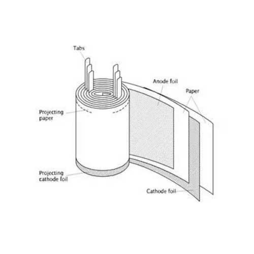
The fifth step: winding of electrolytic paper.
The electrolyte in the capacitor is not directly poured into the capacitor, and the aluminum foil is immersed in a liquid state, but the electrolytic paper that has absorbed the electrolyte is laminated with the aluminum foil layer by layer. Among them, the formula of electrolytic paper and ordinary paper are somewhat different, and are microporous. The appearance of the paper is not as good as impurities, otherwise it will affect the identity and performance of the electrolyte. In this step, the electrolytic paper that has not absorbed the electrolyte is attached to the aluminum foil, and then rolled into the capacitor shell to form the aluminum foil and the electrolytic paper to form a “101010” partition.
Step 6: Impregnation of electrolyte.
When the electrolytic paper is wound up, the electrolyte is poured into it, so that the electrolyte is impregnated on the electrolytic paper. With the innovation of electrolyte formulations and the improvement of electrolytic paper manufacturing skills, the current ESR value of aluminum electrolyte capacitors has also been gradually improved, making it a fraction of the past.
Step 7: Assembly.
This step is to assemble the aluminum shell on the surface of the capacitor and connect the external leads at the same time. The capacitor has been completely formed by then.
Step eight: curling.
If it is the kind of “skinned” capacitor, it is necessary to pass this step to cover the surface of the capacitor with a PVC film on the surface of the capacitor aluminum shell. However, the current use of PVC film capacitors has become less and less, mainly because this material is not in line with the trend of environmental protection, and it does not have much to do with performance.
Step 9: Combine assembly.
Step 10: Charging and aging test.
Step 11: Parameter review.
3DF review: temperature 25 ℃, frequency 120HZ, non-polarity usually 1KHZ (test condition), briefly note: a capacitor will naturally cause a dissipation factor in the electronic circuit. Dissipation and loss are both meaningless in Chinese meaning, it It uses the opposite side in the trigonometric function to find the value. DF is the term used in the Taixi area. The angle represents “%” as a percentage. Tan δ is the term used in the Ritang area. It is expressed with a small number of points. The smaller the value, the better. The R & S capacitor should be discharged before testing the capacity DF, so as to destroy the instrument due to the voltage flowing into (introduced) by the capacitor itself.
Outside review: that is, the aesthetic appearance of the capacitor (beauty pager). It must be judged by our vision. It turns out that in every process in front of us, we know what is a good product or what is a bad product. Except, but in order to guard against the “dog of the bereavement” (some bad products are not noticed), some still need to review the outside, just in case.
Xuansn is a company with 16 years of experience. In the manufacturing process of aluminum electrolytic capacitors, the process is more sophisticated and strict, and its service and after-sales are more perfect.