When evaluating ripple, it is usually performed around the two components of ripple voltage and ripple current. In most applications, ripple is a circuit condition that engineers want to minimize. For example, in an AC-DC converter that converts AC power to a stable DC output, every effort is made to avoid a phenomenon in which AC power is superimposed on the DC output with a small, frequency-dependent signal. However, in other cases, the ripple can be a necessary design function. For example, a clock signal or a digital signal can use the change in the voltage level to switch the state of the device.
In the latter case, the ripple consideration can be quite simple: Do not let the peak voltage exceed the rated voltage of the capacitor. However, it is important to keep in mind that the peak voltage is the sum of the highest ripple voltage and the DC bias voltage in the circuit. In addition, there is another area where electrolytic capacitors using tantalum, aluminum, and niobium oxide technologies require special attention: Do not let the minimum value of the ripple voltage drop below the zero potential because this will cause the capacitor to work in reverse. Biased conditions. This requirement also applies to Class II ceramic capacitors for low frequency applications.
The capacitors act as charge reservoirs, which are charged when the voltage increases; they discharge to the load when the voltage decreases; they essentially act as smooth signals. The capacitor will experience varying voltages, and depending on the applied power, there may also be varying current, as well as continuous and intermittent pulsating power. Regardless of the input form, changes experienced in the capacitive electric field will cause the dipole oscillations in the dielectric material to generate heat. This reaction, known as self-heating, is one of the main reasons why dielectric properties are an important indicator, because any parasitic resistance (ESR) or inductance (ESL) will increase energy consumption.
Dielectrics with low loss (ie, low ESR/DF and low ESL) will have less heat generation than high ESR and DF dielectrics; however, these parameters also vary with frequency because different dielectric materials provide the best performance at different frequency ranges, respectively ( That is, heat is minimal).
Capacitive dielectrics are thin and may account for only a small fraction of the total mass of the capacitor, so other materials used in the structure must also be considered when evaluating ripples. For example, a capacitive plate in a non-polarity capacitor (such as a ceramic or film capacitor) is metal; and a polar capacitor (such as tantalum or aluminum) has a metal anode (in the niobium oxide technology, the anode is a conductive oxide). And a semiconductor cathode (such as manganese dioxide or conductive polymer). On the external connections or pins, there are also various conductive contacts, including metals (such as copper, nickel, silver palladium, tin, etc.) and conductive epoxy. When AC signals or currents pass through these materials, they all have A certain degree of fever.
To understand how these factors work, we use a solid tantalum capacitor to smooth the residual AC ripple current at the output stage of the DC power supply as an example. First, because this is a polarity technique, a positive voltage bias is needed to prevent the AC component from causing reverse bias conditions. This bias voltage is usually the rated output voltage of the power supply.
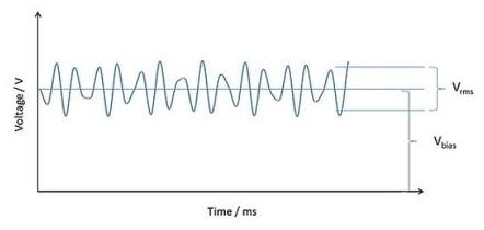
Figure 1: The ripple voltage is superimposed on the bias voltage.
Voltage: Voltage
Time: Time
Before we consider the ripple, we must pay attention to the heat generated by the applied DC bias. Capacitance is not an ideal device. A parasitic phenomenon is the shunt resistance across the dielectric material, which will cause leakage current (DCL) to occur. This small DC current can cause heating, but unlike other typical application ripple conditions, this heating is usually negligible. A 100uF/10V SMD tantalum capacitor has a DCL of less than 10uA (100uA@85°C) at room temperature, so its maximum power dissipation is 1mW.
Next, we look at the power consumption (equal to I2R, where “I” is the current root mean square [rms]) resulting from the ripple value of the current at a given frequency (equal to “R”, the ESR of the capacitor at the same frequency). .
We start by looking at a sinusoidal ripple current and its RMS equivalent. If at a certain frequency, we make a current of 1A Irms flow through a 100mΩ ESR capacitor, its power consumption is 100mW. With continuous power supply, based on the thermal capacity of the capacitive element structure and the package material, as well as all the measures taken to dissipate heat to the surroundings (for example, a combination of convection, conduction, and radiation), the current will cause the capacitor to heat internally until it reaches the surrounding environment. balance. In this case, the ripple heat is 100 times higher than the DC leakage current, so the latter (as described above) is negligible. However, when evaluating a new capacitor, it is always a good idea to check the DC leakage current heating.