A board boots in a quiet lab and the engineer hears a faint buzz. Or a new product comes back because owners complain of a high-pitched whine. In both cases the source is usually the same: a multilayer ceramic capacitor sitting on a power rail.
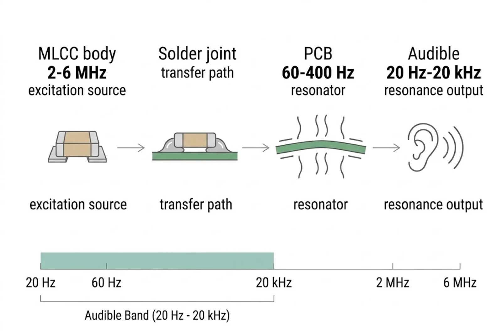
MLCC acoustic noise happens because barium titanate ceramic changes shape slightly when voltage is applied. That movement passes through the solder joint into the board, and the board, being large and thin, pushes air at a frequency you can hear. The capacitor is the source, the solder joint is the path, the PCB is the speaker.
The fix follows the same three links. This article walks the chain from the excitation to the sound, then covers what actually stops it and what each option costs.
From MHz Vibration to Audible Whining
A singing capacitor does not make noise on its own. Acoustic noise in an electronic assembly comes from a three-part chain: the MLCC as the excitation source, the solder joints as the transmission path, and the printed circuit board as the acoustic resonator.
- The MLCC as source. The dielectric is based on barium titanate (BaTiO3), a ferroelectric with a high dielectric constant. Under an alternating field the crystal structure deforms microscopically, and the body vibrates at the drive frequency.
- The solder joint as path. The MLCC is surface-mounted, bonded to the pads with tin-lead or lead-free solder. Those fillets are a rigid mechanical link, so expansion and contraction at the terminals goes straight into the pads.
- The PCB as resonator. An FR4 board behaves like a soundboard. Forces arriving through the solder joints drive bending modes across the substrate, and the board pushes air. Without the board, a chip that small could never move enough air for anyone to hear it.
Why the Frequencies Do Not Seem to Match
A regulator running at 500 kHz or 2 MHz should not produce a sound at 8 kHz. The explanation sits in three frequency ranges that never overlap.
| System Component | Typical Frequency Range | Human Audibility | Engineering Relevance |
|---|---|---|---|
| MLCC thickness-mode resonance | ≈ 2–6 MHz | Inaudible | Estimated for 0.4 mm to 1.1 mm thickness at about 4500 m/s sound velocity in BaTiO3. The natural resonance of the ceramic chip itself. |
| PCB bending and flexing modes | ≈ 60–400 Hz | Inaudible on its own | First bending mode of 1.6 mm FR4 boards from 100×150 mm to 300×300 mm, E ≈ 24 GPa. Needs continuous low-frequency excitation to make sound. |
| Voltage modulation and load envelope | 20 Hz–20 kHz | Fully audible | Set by the application behavior: sleep states, light-load PFM burst cycles, PWM dimming. This sits directly in the hearing range. |
The MLCC’s own resonance at 2 to 6 MHz is far above hearing, and the board’s flex modes at 60 to 400 Hz need sustained slow excitation. What you hear is neither. It is the modulation applied to the capacitor. When a converter drops into a low-frequency state, such as PFM bursting at light load or PWM backlight dimming, it applies a fluctuating envelope across the part. The vibration follows that envelope, and the board turns it into a buzz.
Piezoelectricity vs Electrostriction
Two different field-induced strain mechanisms drive the sound. Because the dielectric layers are very thin, the x and y field components can be ignored and only the vertical axis matters.
The governing relationship for mechanical strain sz in the ceramic layers is:
sz = d33 · Ez + M33 · Ez²
Here sz is mechanical strain, d33 the piezoelectric coefficient, M33 the electrostriction coefficient, and Ez the z-axis electric field.
The first term is proportional to the field and vibrates at the drive frequency. The second is proportional to the square of the field, so it produces a second harmonic, twice the drive frequency. Neither 500 kHz nor its 1 MHz harmonic is audible. The sound arrives from the low-frequency envelope of Ez, not from either term directly.
That is why power state matters more than switching frequency. A buck regulator in standby leaves continuous PWM and switches to pulsed PFM, sending short bursts separated by idle periods. The burst cycle becomes an envelope that drives the voltage up and down at an audible rate, and the capacitor responds to that slower pattern. A laptop whining in sleep mode is doing exactly this.
What Makes an MLCC More Likely to Sing
Not every capacitor on a board becomes audible. Several factors decide the outcome.
- Class II dielectrics. X5R, X7R and Y5V buy high capacitance in a small package by relying on barium titanate, which is strongly piezoelectric. Class I types such as C0G are based on non-ferroelectric material and stay quiet, at the cost of much lower capacitance per unit volume.
- Package size. An 0201 or 0402 has little surface contact and generates little force. A 1206 or 1210 has more mass, a larger solder footprint, and pushes far more energy into the board.
- Parallel parts on one rail. Laptop battery lines, CPU VRMs and power inputs often carry several 10 µF or 22 µF parts in parallel. Under the same fluctuating voltage their vibration adds up, turning a whisper into a whine.
- Voltage swing. Mechanical force tracks the change in voltage. Fast switching transients, load steps and PWM dimming all increase the swing, and with it the vibration.
What Each Fix Buys, and What It Costs
Noise reduction has to be weighed against unit cost. Quiet parts exist, but none of them are free.
| Suppression Approach | Typical Noise Drop | Cost Position | Tradeoffs |
|---|---|---|---|
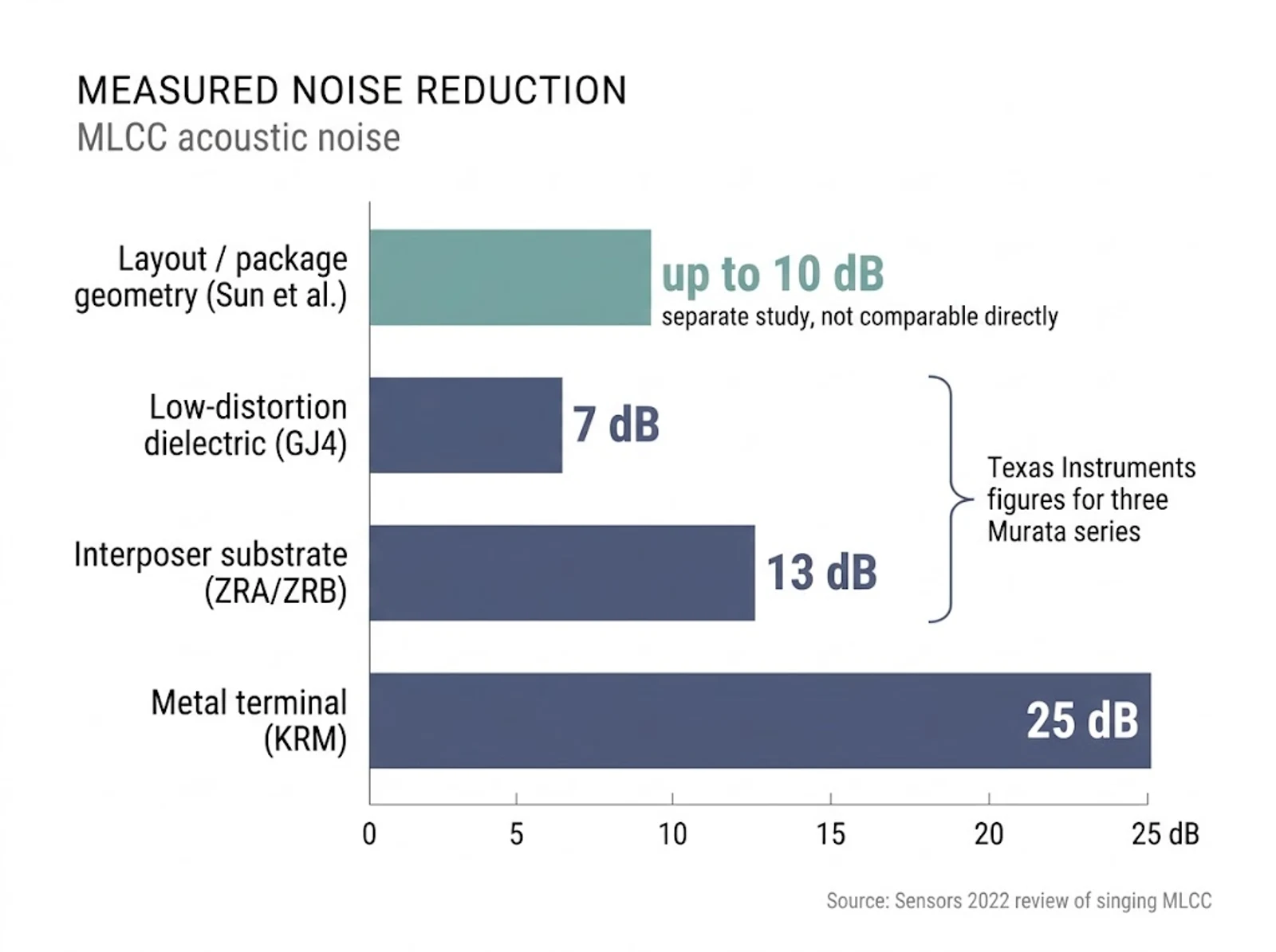
| Low-distortion dielectric (GJ4 type) | −7 dB | Lowest of the three | Uses a lower-distortion material, at the price of less capacitance in the same package. A simple swap when a moderate reduction is enough. |
| Interposer substrate (ZRA/ZRB type) | −13 dB | Higher than GJ4 | A small intermediate board absorbs strain before it reaches the main PCB. Effective, but adds component height and raises unit cost. |
| Metal terminal / lead frame (KRM type) | −25 dB | Highest. Texas Instruments warns these parts are expensive. | Flexible terminals lift the ceramic body off the board and absorb nearly all the vibration. Ko et al. note these parts need additional manufacturing control, because insufficient solder can let the capacitor detach. |
| Layout and package geometry (Sun et al.) | Up to −10 dB | No added piece cost | Compared three-terminal, reverse-geometry and interposer packages against a standard part. Reverse geometry was the least effective, three-terminal and interposer the most. Results vary by layout and capacitor type. |
The decibel figures above come from two separate studies and should not be read as one ranking. The 7, 13 and 25 dB values are what Texas Instruments reports for three Murata series. The 10 dB figure belongs to Sun et al. comparing package geometries. Treating them as a single test would overstate the comparison.
One further physical option is thickening the ceramic cover layer. A study found that increasing it by 10% gave a significant improvement without changing the footprint.
Why Per-Part Cost Multiplies
A board rarely carries one singing capacitor. Put twenty or thirty decoupling capacitor positions on a single rail and a premium part at each one becomes a budget problem fast.
The practical order is to fix layout and drive conditions first, since that costs nothing per unit and removes most of the noise, then spend on premium parts only at the positions that still fail validation.
Finding the Culprit on Your Board
The whole board vibrates, so the guilty part is not obvious. Work through it in this order.
- Record it. Put the powered system in a quiet room and capture the buzz with a phone or a high-gain microphone held close to the board.
- Look at the spectrum. Run a basic FFT app on the recording to get the dominant frequency.
- Match it to the circuit. Compare that peak against your backlight PWM, your sleep-state burst pattern, or an intermittent polling cycle.
- Test parts physically. With the system buzzing, press gently on suspect MLCCs with an insulated probe. If the pitch changes or the sound stops, you have found it. Desoldering individual parts one at a time works too.
With lab access, the same procedure scales up. Murata evaluates acoustic noise with an anechoic box, a calibrated sound level meter, a microphone and an FFT analyzer. A laser Doppler vibrometer maps vibration across the board without contact, which shortens the search when several parts are suspect.
When to Change Capacitor Type
If layout and drive changes do not solve it, the remaining option is a different technology. Parts without a ferroelectric dielectric do not have this problem at all.
- Film capacitors. No piezoelectric behavior, so they stay quiet under high AC ripple and pulsing loads. Widely used in mains filtering and industrial power. Larger and more expensive than an MLCC. Our film capacitor range covers these positions, and the capacitor types guide compares the options.
- Aluminum electrolytic. Standard and polymer aluminum parts have no piezoelectric effect, which makes them suitable for quiet supply filtering and low-frequency decoupling. Polymer types add low ESR for modern high-current designs.
- Tantalum and polymer tantalum. High capacitance in a small SMD footprint without the buzz. Watch the voltage derating and the polarity.
- Mixing types. Often the cheapest answer. Keep small MLCCs where only high-frequency bypass matters, and let a larger electrolytic or film part carry the bulk ripple.
Xuansn builds film, electrolytic and custom capacitor configurations, and this kind of sourcing decision is routine work for our engineering team rather than a special case.
Common Questions
Why does my capacitor buzz?
Class II dielectrics such as X7R and X5R contain barium titanate, which is piezoelectric and electrostrictive. An alternating field makes the ceramic expand and contract, the solder joints pass that movement into the PCB, and the board radiates it as sound.
Can MLCC noise damage the capacitor?
Rarely the capacitor itself. The concern is the solder. Sustained mechanical cycling can fatigue the fillets over time, leading to micro-cracking and eventually a joint failure, and stress can spread to nearby parts.
Does X7R sing more than C0G?
Substantially more. X7R is a Class II ferroelectric material chosen for volumetric capacitance, so it responds strongly to both piezoelectric and electrostrictive forces. C0G is Class I and non-ferroelectric, so it stays quiet, but it offers far less capacitance per unit volume and will not carry bulk filtering on its own.
Can I just replace the noisy MLCC with a bigger one?
Usually the opposite. A larger package carries more mass and a bigger solder footprint, so it transfers more energy into the board. Reducing package size, or splitting one large part into several smaller ones, often helps before any change of material is needed.
Dealing with a board that will not stay quiet? Send us the rail, the part list and what you have already tried. Our engineers will work through the alternatives with you and quote the ones that fit. Email [email protected], call +86-769-8166 8821, or send your specification.