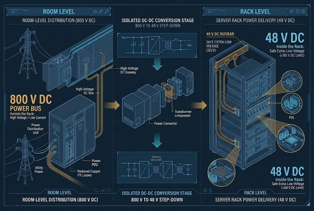
Modern data center power architecture is splitting into two opposite directions at the rack boundary. Outside the rack, room distribution is climbing toward 800 V DC to cut copper losses across long runs. Inside the rack, busbars step down to 48 V DC so technicians can service live blades safely without crossing the 60 V DC touch-safe ceiling.
Every conversion stage burns power as heat, takes board space and adds a failure point. So why not pick one voltage and carry it from the utility transformer all the way to the motherboard? The answer is a conflict between two hard limits: the resistance of copper across a room, and the electrical resistance of the human body inside a cabinet.
The Rack and the Room Want Opposite Voltages
When AI server power demand pushed individual cabinets past 30 kW and toward 100 kW, the legacy power delivery model broke in two places at once. Inside the cabinet, the old 12 V distribution bus required busbars so thick they blocked airflow and still dropped too much voltage before reaching the compute trays. Out on the data hall floor, conventional three-phase AC distribution or 400 V DC feeds required massive overhead cable trays to feed a 1 MW cluster of ten racks.
Fixing both problems meant pushing voltage higher, because higher voltage moves the same watts at lower current. Yet the room and the rack stopped at completely different numbers. Facility engineers are pushing room-level distribution toward 800 V DC, borrowing heavily from electric vehicle charger and traction inverter architectures. Rack architects, on the other hand, moved from 12 V up to 48 V DC and stopped right there.
This creates a horizontal fork in the power tree. Rather than a smooth, uniform rail running through the building, the architecture pulls apart: upward in the facility hall to survive distance, and downward at the rack boundary to survive human contact. Every intermediate DC-DC conversion stage in a modern AI data center exists to bridge the gap between what the room wiring requires and what the rack mechanics allow.
The Current Math That Forces Each Choice
Basic Ohm’s law dictates why neither 12 V nor 48 V can leave the rack, and why 800 V dominates the room. Power equals voltage times current (P = V × I). When power stays fixed at 100 kW for a single high-density rack or 1 MW for a ten-rack row, raising the voltage cuts the current in exact proportion.
| Power Level | 12 V | 48 V | 400 V DC | 800 V DC |
|---|---|---|---|---|
| 100 kW (Single Rack) | 8,333 A | 2,083 A | 250 A | 125 A |
| 1 MW (Cluster) | 83,333 A | 20,833 A | 2,500 A | 1,250 A |
Current reduction is only part of the picture. Resistive heating in a conductor follows the square of the current (P = I²R). If two systems use a copper cable or busbar of the exact same cross-sectional area and length, their resistance (R) is identical. Cutting the current by a factor of four reduces the heat lost in that conductor by a factor of sixteen.
| Voltage | Relative Copper Loss (Same Conductor Cross-Section) |
|---|---|
| 12 V | 4,444× |
| 48 V | 278× |
| 400 V DC | 4× |
| 800 V DC | 1× |
Look at the gap between 48 V and 800 V. For the same conductor size, distributing power at 48 V generates 278 times more resistive heat than distributing it at 800 V. Inside a two-meter tall server rack, a thick vertical copper busbar can carry 2,083 A over a short distance without melting or costing a fortune. Running 20,833 A at 48 V across thirty meters of data hall floor to feed a 1 MW cluster calls for a conductor closer to an industrial smelting plant than to a server hall. Only 800 V DC brings cluster-level current down to 1,250 A, a number that fits into standard overhead busways with manageable thermal loss.
48 V Is a Safety Limit, Not an Efficiency Optimum
If 800 V cuts copper losses by 278 times compared to 48 V, a reasonable question is why rack designers stopped at 48 V instead of running 100 V or 200 V down the backplane. The reason has nothing to do with electrical efficiency. It is a legal and physiological boundary.
Under international safety standard IEC 62368-1, which governs information and communication technology equipment, Energy Source Class 1 (ES1) sets the ceiling for touch-safe direct current at 60 V DC under normal operating conditions. Below 60 V DC, dry human skin offers enough resistance that accidental contact does not drive lethal current through the chest, and service personnel can work around exposed conductors without high-voltage personal protective equipment or strict lock-out/tag-out procedures.
A nominal 48 V DC system does not stay at exactly 48.0 V. When backup battery strings or rectifiers float on the bus, the actual line voltage typically sits around 52.8 V, and transient surges or regulation tolerances push it slightly higher. Choosing 48 V nominal leaves a safe margin below the 60 V DC ES1 hard ceiling.
At 10 kW or 15 kW per rack, 12 V meant roughly 1,000 A, workable with heavy power shelves. At 100 kW it demands 8,333 A. No practical connector can hot-swap a blade at that current without massive contact resistance, and the copper weight alone would exceed floor loading limits. Moving to 48 V cut rack current by a factor of four and I²R busbar losses by a factor of sixteen, right up to the highest voltage permitted for live human maintenance.
Why 800 V Only Works Outside the Rack
Outside the cabinet, nobody hot-swaps bare busbars by hand while the system is live. Room-level power runs inside enclosed overhead busways, armored conduits, and locked power distribution cabinets. Because fingers are kept out by grounded metal enclosures, the 60 V DC touch-safe rule no longer applies, freeing facility engineers to chase the copper math up to 800 V DC.
Bringing that 800 V rail directly into the server compute tray, however, hits immediate mechanical and physical walls:
- Creepage and clearance distances expand dramatically above 60 V. On a dense server motherboard or backplane, 800 V requires wide physical gaps between copper traces to prevent surface tracking and air breakdown, especially as dust and humidity accumulate over years of service.
- Direct current does not cross zero volts the way alternating current does. If a technician pulls a live 800 V DC blade from a backplane, the resulting electrical arc will not self-extinguish; it will sustain a plasma flame capable of vaporizing contacts and causing severe arc-flash injuries.
- High-voltage connectors require deep shrouding, sequenced safety interlock pins, and bulky insulation housings. In a 1U or 2U compute sled where every millimeter of rear panel width is needed for liquid cooling manifolds and high-speed optical transceivers, 800 V connectors simply take up too much space.
So 800 V stays outside the rack, or enters only a sealed, dedicated power shelf where qualified power electronics convert it down to 48 V before it ever touches the open vertical rack busbar.
What Each Voltage Does to the Capacitors
Splitting the building into an 800 V room domain and a 48 V rack domain changes the electrical stress at every conversion boundary. Capacitors sit at each of these boundaries to absorb switching ripple, hold up the rail during brief grid drops, and feed sudden load spikes. Because voltage and current invert as power moves from the wall to the silicon, the capacitor technologies must shift at every step. For a longitudinal look at how a single rail steps down, see our guide on which capacitors fit each power stage.
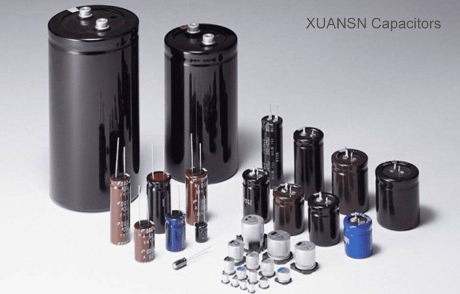
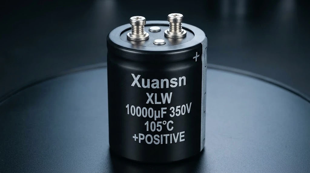
At the AC-to-800 V DC rectifier stage (or active front end), the primary challenge is high voltage combined with continuous switching ripple current and bulk energy storage requirements. A single 800 V bus often splits into two 400 V halves in series or uses high-voltage stacks. Here, engineers rely on large can XLW screw-terminal capacitors rated at 400 V to 500 V per cell, alongside heavy-duty polypropylene DC-link capacitors. The main constraint here is internal self-heating from ripple current: if the equivalent series resistance (ESR) is too high, core temperatures climb past 105 °C and dry out the electrolyte prematurely.
At the 800 V-to-48 V isolated DC-DC converter stage, power crosses the galvanic safety barrier that separates the dangerous room bus from the touch-safe rack bus. These high-density resonant (LLC) converters operate at hundreds of kilohertz to shrink the isolation transformer. The input side needs high-voltage, low-inductance capacitance that fits into a low-profile power shelf, while the output side suddenly faces thousands of amps of combined current at 48 V. You can read a deeper breakdown of the role of aluminum electrolytic capacitors in 48 V and 800 V data center power on our companion technical site.
Once power lands on the 48 V rack busbar and enters the server tray, the capacitor job shifts to local energy buffering. Snap-in and conductive polymer hybrid aluminum electrolytic capacitors rated at 63 V to 100 V sit at the tray input and around the 48 V intermediate bus converters (IBC). Their task is to keep the 48 V rail stiff when all eight GPUs in a node slam from idle to full load at the same millisecond, preventing voltage droop from tripping under-voltage lockouts.
Finally, at the point-of-load (POL) stage right next to the processor package, voltage drops below 1.0 V and current surges into the thousands of amps per chip. Electrolytic cans are far too slow and inductive here. This domain belongs entirely to multi-layer ceramic capacitors (MLCCs) and low-profile conductive polymer tantalum or aluminum chips. At this millimeter scale, parasitic inductance and microsecond transient response govern everything, a dynamic we covered in detail under GPU VRM decoupling.
Where the Conversion Losses Stack Up
A common objection to the 800 V-to-48 V architecture is that it still uses three major conversion blocks from the AC utility feed to the processor core: AC to 800 V DC, 800 V DC to 48 V DC, and 48 V DC to sub-1 V POL. Why does this beat the older AC to 400 V DC to 12 V to POL chain?
The difference comes down to converter physics at higher voltages and the elimination of massive distribution losses between the stages. Typical conversion efficiencies across the two chains fall in the range of the figures below (note that these are typical architectural benchmarks, not measured test data from a specific vendor):
| Architecture | Stage Efficiencies (Rectifier / Intermediate / POL) | Total End-to-End |
|---|---|---|
| AC → 400 V DC → 12 V → POL | 98.0% / 97.0% / 94.0% | 89.4% |
| AC → 800 V DC → 48 V → POL | 98.0% / 98.5% / 96.0% | 92.7% |
A jump from 89.4% to 92.7% looks modest on paper until you apply it to a 10 MW data hall. That 3.3 percentage point gain saves 330 kW of continuous waste heat—and saves another 50 kW to 100 kW of chiller and pump power that would have been required to remove that heat from the building. The 800 V-to-48 V intermediate stage hits 98.5% typical efficiency because wide-bandgap semiconductors (SiC and GaN) switch 800 V with very low conduction loss, and outputting at 48 V instead of 12 V cuts secondary rectifier currents by a factor of four.
What This Means for a 2026 Build
For hardware teams and power supply buyers specifying equipment in 2026, the rack-versus-room split sets clear boundaries on component sourcing. Most halls in service still feed the rack from AC distribution; the 800 V room bus is where new high-density builds are heading rather than a retrofit every operator has already made. If your rack density stays below 30 kW, conventional three-phase AC distribution into the rack with internal 48 V rectifiers remains practical and avoids facility-wide DC retrofits. Once single-rack power passes 50 kW and clusters scale to 1 MW and beyond, keeping AC or 400 V DC in the room forces unacceptable copper cross-sections and voltage drops.
On the component side, power supply BOMs are polarizing into two distinct voltage classes. On the high-voltage side of the rack boundary, engineers need 450 V to 500 V rated screw-terminal aluminum electrolytics and 800 V to 1,200 V DC-link films designed for continuous high-ripple operation at 105 °C. On the low-voltage side inside the cabinet, the old 16 V and 25 V capacitor bins used on 12 V rails are obsolete for new designs, replaced by 63 V, 80 V, and 100 V rated snap-in and conductive polymer parts that give safe derating margins on a 48 V bus.
Where This Sits in the AI Power Series
Our previous articles in the AI power series traced why compute power is rising, how switching converters rely on energy storage, how a single voltage rail steps down from 380 V to 1 V across four capacitor layers, and how GPU decoupling responds across nanosecond-to-microsecond time windows. This article looked horizontally across the data center floor to explain why the facility room and the server rack refuse to meet at a single voltage, and how that 800 V / 48 V split shapes the converters and capacitor banks standing between them.
Common Questions
Can 48 V power a GPU directly without another conversion stage?
No. Modern GPU cores operate at roughly 0.6 V to 1.0 V because lower voltage reduces dynamic switching losses inside nanometer-scale transistors (which scale with V²). Applying 48 V directly to a processor core would instantly punch through the microscopic gate oxides and destroy the silicon. The 48 V bus must step down through intermediate bus converters and multiphase point-of-load voltage regulators right on the GPU board before entering the package.
What is the biggest obstacle to bringing 800 V directly inside the server rack?
Human maintenance safety and arc-flash physics are the primary blockers. Above 60 V DC, equipment exceeds the IEC 62368-1 ES1 touch-safe limit, meaning technicians could no longer hot-swap server blades or work inside an open cabinet without high-voltage protective gear and strict lock-out procedures. In addition, 800 V DC requires wide creepage distances that waste board space and creates sustained DC arcs if a connector is pulled under load.
How does the 48 V / 800 V split change capacitor requirements compared to older 12 V servers?
It pushes voltage ratings upward at both ends while increasing ripple current density. Inside the server tray, capacitors that used to sit on a 12 V bus (rated at 16 V or 25 V) must now survive a 48 V nominal bus (requiring 63 V to 100 V ratings) with low ESR in compact packages. At the room and power-shelf level, rectifiers and DC-DC converters feeding an 800 V DC bus require series-stacked 450 V/500 V screw-terminal aluminum electrolytics or high-voltage DC-link film capacitors capable of handling continuous kilowatt-level ripple currents without overheating.
Can an existing AC data center room be retrofitted to 800 V DC?
Yes, typically by installing sidecar rectifier cabinets at the end of each server row rather than ripping out the entire building transformer infrastructure. Facility AC cables feed the row-end rectifier cabinet, which converts three-phase AC into 800 V DC and sends it down a dedicated overhead busway to the high-density AI racks in that row. However, existing AC breakers, transfer switches, and metering equipment cannot be reused on the DC side because DC fault interruption requires specialized arc-quenching switchgear.
If you are evaluating screw-terminal aluminum electrolytic capacitors, snap-in banks, or DC-link film capacitors for 800 V power shelves and 48 V server architectures, our engineering team can help match ripple current, ESR, and lifetime specs to your thermal profile. Reach out through our contact page or email us directly at [email protected] with your operating voltage and ripple requirements.