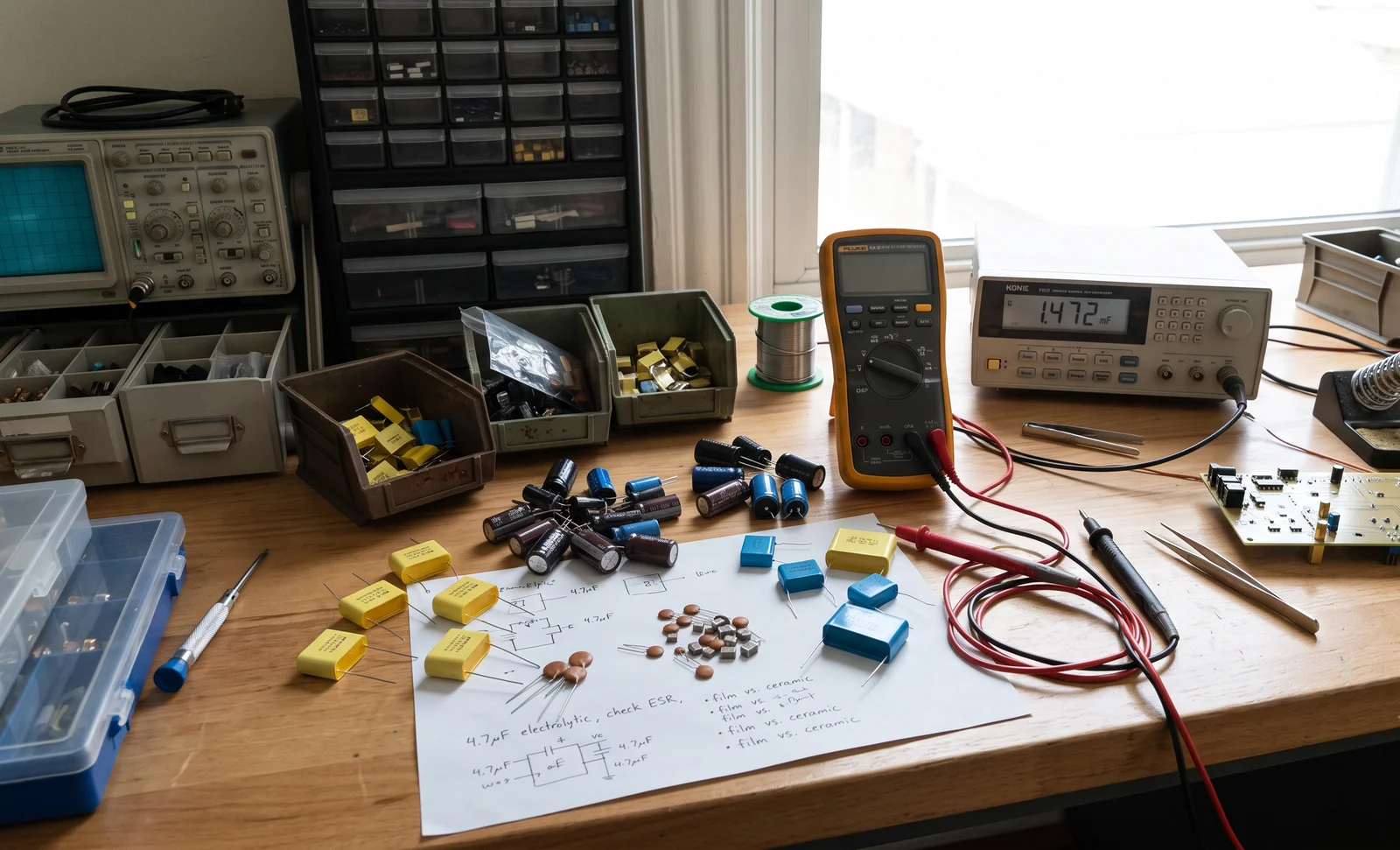
A prototype that works on a breadboard and misbehaves on a printed circuit board is one of the oldest frustrations in electronics. The schematic is identical, the components are the same, yet the assembled board resets itself intermittently or fails EMC testing. Nine times out of ten the cause is not a defective part but missing decoupling: the small ceramic capacitors that should sit within a few millimetres of every integrated circuit’s power pin are absent, placed too far away, or carrying the wrong value.
This guide explains what a decoupling capacitor actually does, why 0.1 µF became the industry default, how to place it, and — for engineers who buy components rather than design them — what to look for when sourcing these parts in volume.
What a decoupling capacitor does at an IC power pin
A decoupling capacitor performs two jobs at the power pin of an integrated circuit. The first is local energy storage. Digital logic switches state in nanoseconds, and each transition draws a short, sharp current spike that a power supply sitting centimetres away cannot deliver quickly enough. The capacitor parks a small charge next to the chip and releases it at the instant the current is demanded, holding the rail above the IC’s minimum operating voltage. Without it, the rail sags, and the chip either misbehaves or resets.
The second job is noise filtering. The capacitor presents a low-impedance path to ground for high-frequency noise, so switching noise generated inside the IC does not travel back out along the power distribution network, and supply noise from elsewhere does not ride into the chip. In this role the same component is often called a bypass capacitor — it “bypasses” unwanted alternating current around the active device.
Decoupling and bypassing: two names, one part
There is no physical difference between a decoupling capacitor and a bypass capacitor; the distinction is positional. A bypass capacitor shunts high-frequency noise on a signal or supply line to ground, while a decoupling capacitor isolates one stage of a circuit from another by stabilising a local DC rail. The dictionary definition of a bypass capacitor — a capacitor employed to conduct alternating current around a component or group of components — notes that the same device is “also referred to as a decoupling capacitor.” In practice, engineers use “decoupling” for the capacitor at an IC power pin and “bypass” for one on a signal path, but the part on the shelf is the same low-ESR ceramic.
Why 0.1 µF became the standard value
0.1 µF is the conventional per-IC decoupling value, and it survives because it fits the physics of high-frequency supply current. A real capacitor is not a pure capacitance: it carries parasitic equivalent series resistance (ESR) and equivalent series inductance (ESL). Above its self-resonant frequency the component stops behaving like a capacitor and starts behaving like an inductor, at which point it can no longer deliver instantaneous charge. A 0.1 µF ceramic resonates comfortably above the switching frequencies of most digital logic, which is why a single 0.1 µF part close to the supply pins is adequate for circuits operating up to roughly 50 MHz.
For the same reason, capacitance is not a case of “the more the better.” A larger capacitor stores more charge but resonates at a lower frequency and, in a physically bigger package, carries more ESL — so at the exact frequency where a small part is effective, a large one can be nearly useless. This is why PCB designers pair a small high-frequency capacitor with a large bulk capacitor rather than relying on one large value.
One capacitor is rarely enough: the multi-value rule
Because every real capacitor loses its filtering ability above its self-resonant frequency, and because capacitors of different values resonate at different frequencies, designers place several values in parallel to widen the frequency range the network can handle. A common combination is a 0.1 µF ceramic for high-frequency spikes at every power pin, a 0.01 µF or 1 nF part where extra high-frequency filtering is needed, and a 10 µF bulk capacitor near the board power entry to handle slower, stronger switching currents.
Parallel capacitors add their capacitance, and — like parallel resistors — their combined ESR and ESL drop, which lowers the impedance of the local supply rail. The small parts go closest to the IC pins; the bulk part goes where the board is powered. Getting this stack right usually matters more than the exact capacitance at any single position.
Placement matters more than value
Decoupling fails far more often from bad placement than from a wrong component. The rules are simple and worth repeating:
- Place the 0.1 µF capacitor as close as physically possible to the IC’s power and ground pins, with the shortest possible traces.
- Use small package sizes for the high-frequency roles — an 0402 part carries less ESL than an 0603 or 0805, so it decouples better at high frequency.
- Keep the loop area between the capacitor and the IC small; a long, high-inductance path is exactly the failure that a breadboard hides and a PCB exposes.
- Reserve the larger bulk capacitor for the supply entry point or voltage regulator output, not the IC pin.
The breadboard-versus-PCB symptom described at the start of this article is the classic signature of inadequate decoupling: the long, inductive wiring of the breadboard masks the problem, while the fast edge rates of a real board reveal it as voltage dips, ringing, intermittent resets, or conducted-emission failures. Adding a 0.1 µF capacitor next to each offending IC and an adequate bulk capacitor is the usual fix.
Choosing a decoupling capacitor as a buyer
When you move from the schematic to a purchase order, four parameters deserve attention.
Dielectric: X7R, X5R, or COG
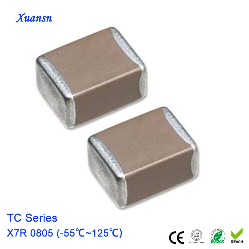
For digital decoupling, X7R is the workhorse — it offers a good balance of capacitance density, cost, and stability from -55 °C to +125 °C, with a capacitance change of roughly ±15% over temperature. X5R is slightly cheaper with a narrower temperature range (±15% from -55 °C to +85 °C), while COG (NP0) is far more stable and drifts almost nothing with voltage or temperature but costs more and stores less capacitance per volume. Most boards need only X7R or X5R; COG is reserved for timing and RF circuits where stability is the requirement.
Voltage rating and derating
Class 2 ceramics lose capacitance as DC bias rises — an X7R part can lose 20% or more of its rated capacitance at half its voltage rating. Selecting a capacitor rated comfortably above the rail voltage (typically 1.5× to 2×) keeps the effective capacitance near the nominal value and adds headroom for transients.
Package size
Smaller packages mean less ESL and better high-frequency performance, but they also mean thinner dielectric and, for Class 2 dielectrics, more capacitance loss under bias. The sweet spot for most 0.1 µF decoupling is 0402 or 0603; bulk values such as 10 µF usually come in 0805 or 1206.
Batch sourcing
For volume buyers the practical questions are consistent — same dielectric, same tolerance, same reel date code. If you need a matched run for a production board, confirm the dielectric and tolerance on the datasheet rather than assuming two parts with the same capacitance are interchangeable. Our MLCC X7R 0805 25V 10 µF capacitor is a typical bulk value, and the MLCC Z5U 0402 1000pF represents the small high-frequency end of the same family.
Common decoupling mistakes in one list
- Using a single large value where several small parts are needed — the rail sags at exactly the frequency that matters.
- Placing the capacitor far from the pin, trusting the schematic over the layout.
- Ignoring the dielectric — substituting a high-loss or unstable ceramic where an X7R is expected.
- Forgetting the bulk capacitor at the board power entry, so switching loads drag the whole rail.
- Sourcing by capacitance alone, ignoring ESR and ESL differences between manufacturers and families.
If you are specifying decoupling or any other ceramic for a production run, our SMD capacitor range covers the common MLCC values and dielectrics, and the multilayer ceramic capacitor category lists the wider ceramic portfolio. Send us your BOM and target price, and we will quote against the exact dielectric, tolerance, and reel requirements.