🔆With the continuous advancement of ceramic capacitor manufacturing technology, various new Types of Ceramic Capacitors have appeared. There are mainly multilayer ceramic capacitors, large size multilayer ceramic capacitors, flexible terminal ceramic capacitors, open circuit ceramic capacitors, feedthrough capacitors, chip feedthrough capacitors, balanced wire feedthrough capacitors, large capacitance ceramic capacitors, etc.
🍒Multilayer Ceramic Capacitors
Multilayer ceramic capacitors are a landmark milestone in ceramic capacitor manufacturing technology. By using lamination technology, the capacitance of ceramic capacitors can be increased by dozens or even thousands of times under the same electrode plate area.
🍬1. Structure of multilayer ceramic capacitors
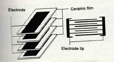
The basic method to increase the capacitance is to try to increase the plate area. It is an effective method to use multiple “capacitors” in parallel to increase the capacitance. The basic structure is shown in the figure below.
According to the formula for calculating the capacitance of the capacitor:
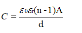
It can be seen that if the electrode spacing is made very thin (the d value is small, as long as the medium can meet the withstand voltage requirements), when the withstand voltage is only 6.3V or lower, the medium only needs 3um. Now the Class Ⅱ of ceramic dielectric can achieve this thickness. If the electrode can also achieve a thickness of 0.05um, a capacitor with a thickness of 1.5mm can be stacked 300 layers. Equivalent to the parallel connection of 300 capacitors, the relative permittivity of the Class Ⅱ of ceramic dielectric can reach 10,000. In this way, the capacitance of 100uF can be done.
The cross-section of a MLCC can be seen as consisting of an entire ceramic block with comb-like junction electrodes, which are electrically connected to the surface of the end of the ceramic block by sintering in the metal layer. The principle structure of a multilayer multilayer capacitor is shown in the figure below.

The packaging forms of multilayer ceramic capacitors mainly include lead type and chip type. The lead type used to be called monolithic capacitor. It is called a monolithic capacitor. Simply put, removing the leads of the monolithic capacitor is a form of SMD packaging. In fact, the development of packaging is indeed such a process. If the leadless resistors and capacitors in the past were all to obtain better high-frequency performance, and to ensure the robustness of the external electrodes, the external electrodes of passive chip devices were specially treated.
🍬2. Improvement of Frequency Characteristics of Multilayer Ceramic Capacitors.
The parasitic inductance is much reduced because the lead wire is removed from the multilayer ceramic capacitor. For the lead wire, the inductance of about 1mm length will be 1nH, so the influence of the lead wire of different length on the frequency characteristics is shown in the figure below.
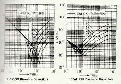
It can be seen from the figure that the resonant frequency of 1nF (1000pF) with C0G dielectric ceramic capacitors without leads is about 130MHz, and when the lead length is 1.5mm, the resonant frequency drops to about 100MHz. The lead lengths are respectively 5mm and 10mm. The resonant frequency at 20mm and 20mm drops to below 70MHz, 50MHz and 33MHz respectively; the resonance frequency of 100nF X7R dielectric ceramic capacitor without lead is about 13MHz, when the lead length is 1.5mm, the resonance frequency drops to 9MHz, and the lead length is respectively When it is 5mm, 10mm, and 20mm, the resonant frequency drops below 7MHz, 5MHz, and 4MHz, respectively. It can be seen that the smaller the capacitance, the greater the influence of the lead length on the resonant frequency of the capacitor itself, that is, the worse the characteristic becomes. At 1nF, the 5mm lead wire can reduce the resonant frequency of the capacitor to half, that is, the usable frequency of the capacitor is reduced to half. At the same time, the impedance at the resonance point becomes high. This shows that in the application of high frequency, especially ultra-high frequency, the wiring length of the lead or PCB has a great influence on the circuit. When the frequency is not too high, although the influence of the lead length on the frequency characteristics of the capacitor becomes smaller, it can be seen in the table that the lead length of 5-10mm is enough to halve the resonant frequency of the capacitor, even if the capacitor is bypassed. In the application, this also shows that the narrowing of the bypassable frequency band is still detrimental to the performance of the circuit. Therefore, in applications, it is best not to use lead-type devices if chip devices can be applied, which is one of the advantages of multilayer ceramic capacitors.
🍒Low Inductance Packaged Ceramic Capacitors
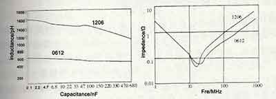
🍬As can be seen from the above, the parasitic inductance of the lead wire of the ceramic capacitor can reduce the self-resonant frequency of the ceramic capacitor, and the reason is the additional parasitic inductance caused by the lead length. When the multilayer ceramic capacitor works at a very high frequency, in addition to the hope that the lead has a smaller parasitic inductance, the parasitic inductance caused by the length of the multilayer ceramic capacitor cannot be ignored. The parasitic inductance of the 1206 packaged multilayer ceramic capacitor is about 1.6nH, and the resonant frequency of the 0.1uF 1206 packaged laminated ceramic capacitor is about 12MHz. If lower parasitic inductance is required, the 1206 package will not be able to do it. Since the parasitic inductance of the multilayer capacitor is caused by its own length, if the length can be shortened, the parasitic inductance can be reduced accordingly. The most typical method is to change the ends of the multilayer ceramic capacitor from both sides of the long end to the short end. At this time, the size of the package changes from 1206 to 0612, as shown in the following figure.
Low inductance packaged laminated ceramic capacitors are available in 0508 and 0612 sizes.
🍬As the distance between the two electrodes is shortened, the parasitic inductance is reduced by about half, so that the resonant frequency of the capacitor will increase to 142% to 150% of the original 1206 package, as shown in the figure below.
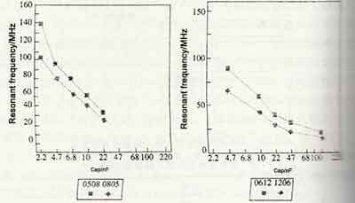
🍬The relationship between the resonant frequency and capacitance of a low-inductance laminated ceramic capacitor is shown in the figure below.
Multilayer ceramic capacitors in the form of low inductance packages are mainly used in occasions where the operating frequency is very high and the peak current generated by the circuit is very high, such as the power supply bypass near the CPU chip of a computer. Possibly reduce the adverse effects of the parasitic inductance of the bypass capacitor.
From the point of view of use, unless the laminated ceramic capacitors packaged with low inductance cannot be used, the multilayer ceramic capacitors in the form of ordinary packages are generally an economical and applicable choice.
🍒Large Size Multilayer Ceramic Capacitors
The capacitance of multilayer ceramic capacitors is getting larger and larger. For example, the maximum capacitance of X7R dielectric laminated ceramic capacitors in 1206 package can only reach 10uF. As the output rectifier filter capacitor has become the best choice. At the same time, application demands require further increases in the capacitance of laminated ceramic capacitors. Generally, the small size package can no longer meet the requirements, and the large size multilayer ceramic capacitors came into being. The basic idea is to increase the package size of multilayer ceramic capacitors and stack several laminated ceramic capacitors together to greatly increase the capacitance of the capacitors.
The largest package size that can be found on the current data is 8060 (20.4mmX15.3mmX2.5mm), and the capacitance is about 100 times that of the 1206 package.
Note that manufacturers of large-capacity ceramic capacitors can use X7R dielectric to make 16V/10F in 1206 packages, while ceramic capacitor manufacturers that are conservative and pay attention to the stability and reliability of capacitors can use X7R dielectrics to make 16V in 1206 packages /2.2uF. If it is available grade Y5V, you can do 16V/47uF, or even 16V/100uF. If you choose the 1812 package, you can get the 50V/2.2uF capacitance specification of the X7R medium, while the 1206 package with the same withstand voltage can only reach 50V/0.68uF; if it is a usable Y5V, you can achieve 50V/100uF.
If it is a higher voltage, such as 500V, due to the increase of the withstand voltage, the thickness of the ceramic dielectric increases, so that the capacitance of the small-sized package laminated ceramic capacitor is very small. For example, the most common 1206 package, the X7R dielectric can generally only reach 500V /0.01uF. If a few microfarads are required, a larger package size is required. Generally, the 7XR medium in the 8060 package can only reach 500V/3.9uF, and the size is only 20.4mmX15.3mmX2.5mm, which is close to or even smaller than the aluminum electrolytic capacitor.
Since the expansion coefficient of the ceramic dielectric is different from that of the epoxy resin circuit board, large-sized laminated ceramic capacitors will generate mechanical stress on the capacitor when the temperature changes relatively large (such as the welding process). If the mechanical stress is too large, the It will tear the ceramic capacitor and cause the failure of the ceramic capacitor. If the laminated ceramic capacitor is welded on the aluminum base circuit board, the laminated ceramic capacitor will be easily torn because the expansion coefficient of the aluminum base circuit board is much larger than that of the ceramic capacitor.
Due to the coefficient of expansion, it is generally not recommended that large size (such as 1812 or larger package size) laminated ceramic capacitors be directly soldered to circuit boards, especially aluminum-based circuit boards.
To prevent ceramic chip capacitors from being torn due to welding or a relatively large operating temperature range, the following solutions can be used.
To solve the problem that large-sized laminated ceramic capacitors and circuit boards are prone to tearing due to the difference in expansion coefficient, several small-sized laminated ceramic capacitors can be stacked to achieve the original large-sized capacitance. , Due to the reduced package size, the failure of ceramic chip capacitors caused by the expansion coefficient problem can be effectively reduced.
In order to obtain a larger capacitance, when a large-sized package is used as a last resort, the pin method can be used to digest the mechanical stress on the pin.
By eliminating the mechanical stress problem caused by the expansion coefficient of ceramic capacitors by means of pins, the package size of the laminated ceramic capacitor can reach 8060, and the number of laminated layers can reach 5. In this way, for ceramic capacitors with 500V withstand voltage, the X7R dielectric can reach 12uF, and the size is 20.4mmX15.3mmX12.5mm, which is close to or even smaller than the aluminum electrolytic capacitor, while the C0G dielectric can reach 0.56uF.
🍒Flexible Terminal Ceramic Capacitors
Since multilayer ceramic capacitors cannot be bent, they may be broken when the circuit board is bent. The larger the size, the greater the possibility of being broken. This is the main reason why large-sized laminated ceramic capacitors are not recommended for general applications.
In order to reduce the possibility of the multilayer ceramic capacitor being broken as much as possible, flexible terminal multilayer ceramic capacitors are introduced, so that the multilayer ceramic capacitor will not be easily broken when the circuit board is greatly bent.
The difference between the flexible terminal multilayer ceramic capacitor and the conventional terminal multilayer ceramic capacitor is that the basic electrode terminal between the electrode and the terminal outer electrode of the flexible terminal multilayer ceramic capacitor adopts a flexible conductive material, which can greatly increase the power consumption. The tolerance of layer ceramic capacitors when the circuit board is bent, the structure of flexible terminal laminated ceramic capacitors is shown in the figure below.
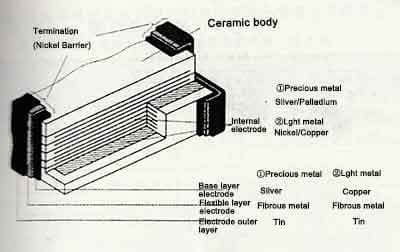
The structure of the flexible terminal multilayer ceramic capacitor is basically the same as that of the conventional multilayer ceramic capacitor. The difference is that the basic electrode of the flexible terminal multilayer ceramic capacitor structure has been changed from nickel to a flexible electrode layer of fibrous metal. In this way, the electrode terminal of the laminated ceramic capacitor with flexible terminal can be deformed under a certain external force, so that the capacitor will not be torn by mechanical stress.
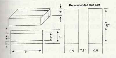
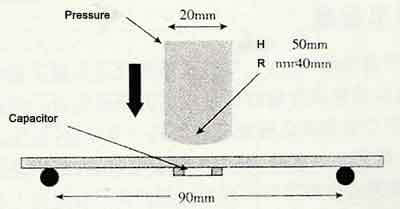
The bending resistance of multilayer ceramic capacitors can be obtained by fracture experiments. The circuit board specifications for the rupture test of multilayer ceramic capacitors are shown in the figure below.

The thickness of the circuit board is 1.6mm, the length is 100mm, the width is 19mm, and the thickness of the copper foil is 0.035mm (1οz). Pads with the same specification as laminated ceramic capacitors are made in the center of the board.
The specific test method is: place the test circuit board on a cylindrical support with a spacing of 90mm, and the laminated ceramic capacitor is below. Use a pressure head with a width of 20mm, a radius of 340mm, and a height of 50mm to press down on the circuit board, as shown in the figure below.
The average board curvature of the laminated ceramic capacitor without tearing is shown in the table below.
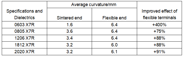
Since the flexible termination absorbs most of the mechanical stress from the bending of the circuit board, the bending degree of the circuit board required for the tearing of the multilayer ceramic capacitor is significantly improved.
🍒Open Circuit Ceramic Capacitors
One of the hidden dangers of multi-layer ceramic capacitors after tearing is that the rupture is at the end terminal. If the laminated ceramic capacitor encounters a humid environment after rupture, it will cause a short circuit between the inner electrode and the outer electrode, resulting in a more serious failure. In order to To avoid such incidents, KEMET, which specializes in the production of military ceramic capacitors, has introduced open circuit capacitors. The internal electrode terminal of the open-circuit capacitor and the external electrode terminal have a safe distance, so when the capacitor is broken, the safe distance can be provided to ensure that the capacitor will not be short-circuited.
🍒Feedthrough capacitor
In order to effectively suppress electromagnetic interference, feedthrough capacitors are often used in applications that require high resistance to electromagnetic interference to ensure that the electromagnetic interference in the transmitted signal or power is effectively filtered out by the feedthrough capacitor. Feedthrough capacitors are a special case of ceramic capacitors. There are common feedthrough capacitors, balanced wire feedthrough capacitors, chip feedthrough capacitors, and chip balanced wire feedthrough capacitors.
🍒Large Capacitance Ceramic Capacitors
With the development of ceramic laminate technology, microfarad ceramic capacitors can be obtained easily and cheaply. Large-capacity “monolithic” capacitors can achieve 100uF.
The dimensions of these ceramic capacitors with pinout are very similar to the size of the chip package of similar specifications, almost like a laminated ceramic capacitor with two leads soldered to facilitate soldering. Another advantage of this lead method is that the lead wire can buffer the mechanical stress caused by the bending of the circuit board and the different coefficient of thermal expansion, and prevent the ceramic capacitor from being torn. “Monolithic” capacitors are widely used as bypass capacitors due to their low price, especially 0.1uF lead-type ceramic capacitors.
🍒Capacitor bank
In some circuit units, multiple capacitors with the same capacitance are often required. In order to reduce the area of these capacitors on the circuit board, multiple capacitors can be made in a standard package, that is, a capacitor row. The shape of the SMD capacitor bank is similar to that of a single SMD capacitor, and it is often used in circuits with limited circuit board size (such as mobile phones, portable electronic devices, etc.).
🍒Temperature Compensated High Frequency Multilayer Chip Ceramic Capacitors
The capacitance change of this type of capacitor changes linearly with temperature, and is mainly used in resonant circuits with large operating temperature changes and high requirements for temperature compensation, such as resonators in TV sets.