Audio circuit principle
The dual-tone multi-frequency signal decoding circuit is an integrated circuit widely used in key telephones (fixed phones, mobile phones), program-controlled switches, and wireless communication equipment.
1. Dual audio decoding electronic circuit
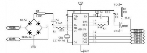
2. Pin 3 receives the dual-tone multi-frequency pulse signal from the phone. The dual-tone multi-frequency signal is first passed through its internal dial tone filter to filter out the dial tone signal, and then pre-amplified and sent to the dual tone filter. Separate the dual audio signal according to the high and low audio signals, and then send it to the output decoding circuit through the high and low group filters and amplitude detectors. After digital calculation, the corresponding output is output at the data output terminal (pin 11 to 14) Of 8421 yards.
The data output terminals Q4~Q1 of MT8870 are connected to the single-chip microcomputer, and the single-chip microcomputer recognizes the 4-bit code. Telephone buttons and corresponding decoding (Q4~Q1) output. R/P, REDIAL, HOLD, HANDSFREE and other functions are used. In order to make the one-chip computer obtain effective data in time, the effective end of CLD of MT8870 is connected to the INT0 pin of CPU after inversion. When the MT8870 obtains a valid dual-tone multi-frequency signal, the CLD level changes from low to high, and then inverts to low. After the CPU detects it, it instructs the input port to receive a valid binary code.
2, TDA2822 dual-channel power amplifier circuit
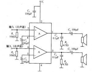
R1 and R2 are input bias resistors, C1 and C2 are grounding capacitors at the negative feedback terminal, C6 and C7 are output coupling capacitors, R3, C4 and R4, and C5 are high-order harmonic suppression circuits to prevent circuit oscillation.
3. Audio amplifier processing circuit
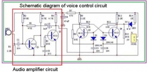
A bistable circuit means that the circuit has two stable states. When there is no signal to trigger, the circuit always maintains a certain stable state. When a signal is triggered, the circuit will jump to another stable state and keep it until a signal is triggered again. . If you don’t understand the bistable circuit, it is recommended to consult more information and get familiar with the bistable circuit first.
The above picture is a bistable circuit composed of transistors Q3 and Q4. The initial state of the circuit can be seen when power is on: Q3 is saturated and turned on first, and the base of Q4 is pulled low, so Q4 is off, and the LED indicator does not light; When the signal is triggered, Q3 is cut off and Q4 is on, so the LED light is on.