Many electronics enthusiasts and repair technicians worldwide face a common challenge when troubleshooting circuits: how to test capacitors effectively.
Capacitors, including electrolytic and ceramic types, are among the most commonly used and easily aged components in electronic devices. A faulty capacitor can cause minor malfunctions or even serious damage, such as burning out the motherboard or power supply.
For beginners, mastering scientific capacitor testing methods—using simple tools like a multimeter or LCR meter—can quickly locate faults and avoid the costly mistake of blindly replacing components.
This guide provides step-by-step instructions on capacitor testing for beginners, helping you identify capacitor problems efficiently and safely—whether you are repairing electronics at home or in a professional workshop.
Before You Test a Capacitor: Safety First
When learning how to test capacitors, safety must come first. Always ensure the capacitor is fully discharged to prevent residual charge from causing electric shock or damaging your multimeter.
Disconnect at least one lead of the capacitor from the circuit to avoid interference from parallel paths. For polarized capacitors (electrolytic or tantalum), double-check the positive (+) and negative (−) terminals to prevent damage. Large-capacity capacitors can be discharged through a resistor, while small capacitors can be safely shorted with a wire.
Never apply voltage exceeding the capacitor’s rated voltage, as this can cause bursting, electrolyte leakage, or fire. When handling high-voltage or high-capacitance capacitors, wear protective gear such as insulated gloves and safety goggles to ensure safe testing.
How to Test Capacitors: Visual Inspection Method (Fast & Beginner-Friendly)
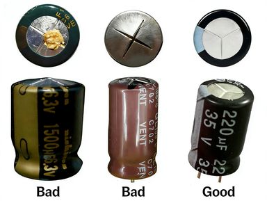
Visual inspection is the fastest way to test capacitors without tools and is widely used as the first step in capacitor testing. It helps quickly identify visible damage in electrolytic, ceramic, and film capacitors, making it ideal for beginners and initial troubleshooting. A capacitor is generally considered normal if it has an intact casing, no bulging, no leakage, clean leads without oxidation, and clear printed specifications. However, visual inspection only checks external condition and cannot confirm full functionality.
Common signs of a bad capacitor include bulging tops, broken vents, or leakage in electrolytic capacitors, and cracked casing, loose leads, or severe oxidation in all capacitor types. These defects indicate internal failure or physical damage, and the capacitor should be replaced immediately. Keep in mind that this method cannot detect issues such as capacitance loss, high ESR, or leakage current, so it should be combined with multimeter testing or LCR measurement for accurate results.
How to Test a Capacitor with a Digital Multimeter (DMM)
Testing capacitors with a digital multimeter is a simple and reliable method for checking capacitor health in electronic circuits. This method works for electrolytic, ceramic, and film capacitors and is suitable for both beginners and electronics enthusiasts.
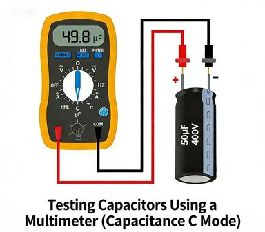
Capacitance Mode (Precise Measurement)
This is the most accurate and commonly used method for testing capacitors. It directly measures capacitance and works for electrolytic, ceramic, film, and tantalum capacitors.
- Fully discharge the capacitor to avoid electric shock and protect the multimeter.
- Set your digital multimeter (DMM) to capacitance mode (F, μF, nF).
- Connect the probes: red to positive (+), black to negative (−) for polarized capacitors.
- Read the capacitance value and compare it with the rated capacitance:
- Value close to the rated capacitance → capacitor is good
- Significant deviation → capacitor may be faulty
⚠️ Capacitance mode provides accurate measurements and is recommended for precise capacitor testing.
Resistance (Ω) Mode (Quick Check)
Use this method when your multimeter does not have capacitance mode. It cannot measure capacitance but can detect faults.
- Fully discharge the capacitor.
- Set the DMM to high resistance mode (×1k or ×10k Ω).
- Connect the probes and observe the resistance:
- Resistance rises from low to high → capacitor is good
- Constant low → capacitor is shorted
- Constant high or no change → capacitor is open or degraded
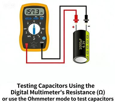
⚠️ Resistance mode is suitable for rough checks only and cannot measure exact capacitance. It is useful for quickly identifying faulty capacitors.
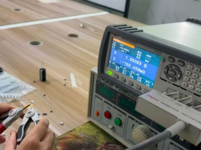
How to Test Capacitors Using a Digital Bridge (LCR Meter)
A digital bridge (LCR meter) provides the most accurate way to test capacitors, measuring not only capacitance but also ESR (Equivalent Series Resistance) and dissipation factor. This method is ideal for professional diagnostics, detecting hidden faults in electrolytic, ceramic, film, and tantalum capacitors, and is especially useful in high-frequency circuits like switching power supplies and motherboards, where capacitor performance is critical.
Steps to Test a Capacitor with a Digital Bridge
- Discharge the Capacitor – Ensure the capacitor is fully discharged to prevent damage or inaccurate readings.
- Set the LCR Meter – Select capacitance mode and choose an appropriate test frequency (e.g., 100Hz or 1kHz).
- Connect the Capacitor – Attach the capacitor to the meter’s test terminals, ensuring correct polarity for polarized capacitors.
- Read and Interpret Results :
- Capacitance within tolerance → capacitor is normal
- High ESR or unstable readings → capacitor is degraded or damaged
Compared with multimeter testing, a digital bridge provides more precise and comprehensive analysis, making it the preferred choice for advanced troubleshooting and quality inspection.
FAQ – How to Test Capacitors
Q1: Can I test a capacitor without a multimeter?
A: You can do a rough visual check for bulging, leakage, cracks, or corrosion, but a multimeter or ESR tester is needed for accurate testing.
Q2: How do I safely discharge a high-voltage capacitor?
A: Use a series resistor, insulated gloves, and tools; never short high-voltage capacitors directly.
Q3: What is ESR and why is it important?
A: ESR (Equivalent Series Resistance) affects capacitor performance and can cause overheating or circuit failure even if capacitance seems normal.
Q4: Can I reverse the probes on a polarized capacitor?
A: No; always connect red → positive (+), black → negative (−) to avoid damage.
Q5: Why does my multimeter show “0” or “OL”?
A: “0” means a shorted capacitor, “OL” means open or not charging; both indicate a faulty capacitor.