Modern metal rolling is performed on rolling mills equipped with automatic thickness and shape control systems (see Figure 1). Flat castings or billets are fed between two counter-rotating rolls. The friction exerted by the rotating rolls typically forces the rolled material into the gap between the rolls. Once in the gap, the rolled material deforms under the combined pressure and friction of the upper and lower rolls. This means that the metal undergoes geometric and dimensional changes under the influence of external forces. This process is widely used in capacitors Production to manufacture high-performance metal electrode materials. XUANSN uses advanced rolling processes in capacitor manufacturing to ensure the mechanical properties and dimensional accuracy of the metal material.
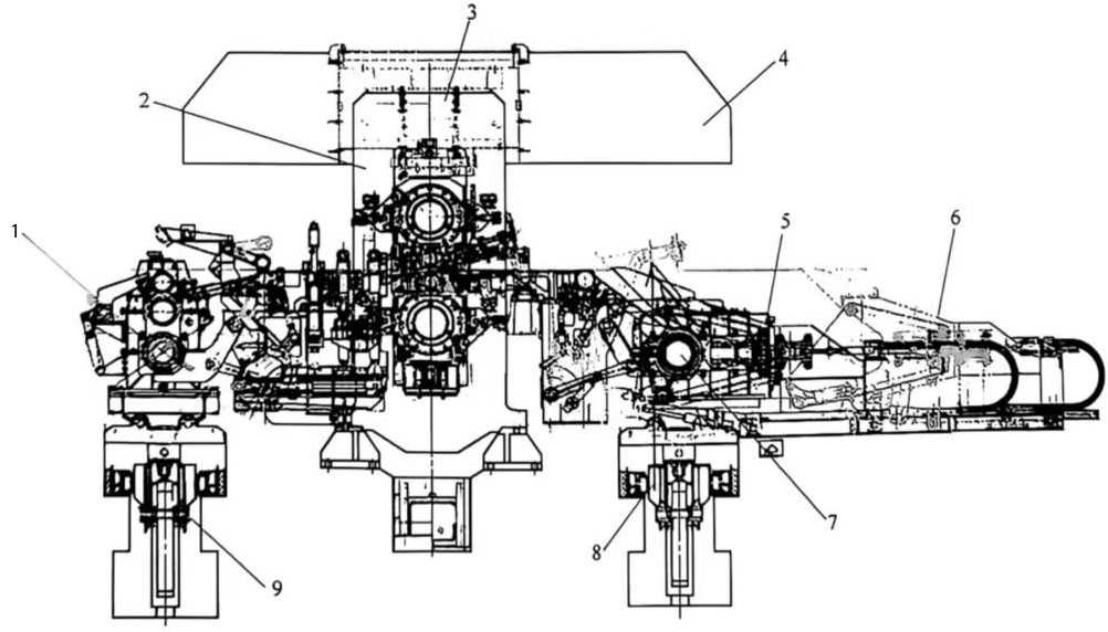
Figure 1 Elevation of 1850mm quadruple irreversible cold rolling mill
1- Uncoiler; 2- Rolling mill; 3- Archway; 4- Exhaust hood; 5- Coiler (position during coiling) 6- Coiler (exit position after coiling); 7- Coiler; 8- Discharge trolley; 9- Feed trolley
1 Elastic deformation
Deformation is divided into elastic deformation and plastic deformation. When the external force disappears, the metal object recovers its original geometric shape and size, which is called elastic deformation. The relationship between elastic deformation and stress is:
![]() (1)
(1)
Where σ-stress;
E-elastic modulus.
That is, stress is proportional to strain, which is the well-known Hooke’s law. In capacitors Production, the elastic deformation of metal materials is the key to ensuring the precise size and structural stability of electrodes.
2 Plastic deformation
Metals deform under the action of external forces. If the metal cannot completely recover its original shape and geometric size after the external force is removed, this deformation is called plastic deformation. The amount of plastic deformation is expressed by the following formula:
![]() (2)
(2)
![]() (3)
(3)
Where b0. Cross-sectional area before deformation;
b1-cross-sectional area after deformation;
l0-length before deformation;
l1-length after deformation.
It is obvious that when an object is deformed, elastic deformation occurs first, followed by plastic deformation. The relationship between stress and elongation when aluminum and aluminum alloys are deformed is shown in Figure 2.
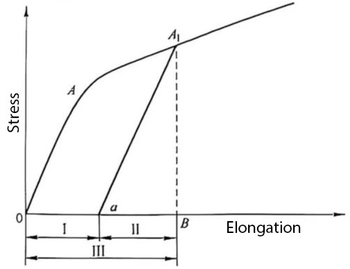
Figure 2 Stress and elongation relationship curve
Ⅰ-elastic deformation part; Ⅱ-plastic deformation part; Ⅲ-total deformation
2.1 Conditions and mechanism of plastic deformation
Plastic deformation is a physical change process. When an object is in a stress state, shear stress occurs on the grain boundary and the slip surface inside the grain (see Figure 3). This stress has a tendency to make it slide relatively along the grain boundary or the slip surface inside the grain. When the shear stress reaches a certain value, it will overcome the resistance of the slip surface or the grain bonding surface and produce plastic deformation of the crystal.
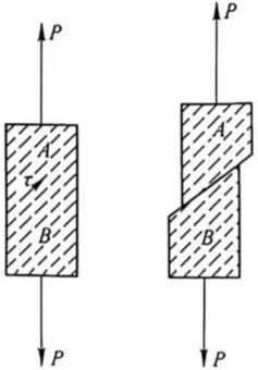
Figure 3 Schematic diagram of crystal slip planes
Atoms within an object are forced out of their equilibrium positions, causing internal forces or stresses to appear within the object. This state is called a stress state. Deformation or fracture at any point in the object is related to the stress state at that point.
Principal stress diagram: The stress state at a point P within an object is represented by the stresses acting on three mutually perpendicular planes. These planes exhibit only normal stresses and no shear stresses. The planes perpendicular to the three planes are used as coordinate axes. These planes are called principal planes. The directions normal to the principal planes are called principal directions, and the normal stresses on the principal planes are called principal stresses, commonly denoted by σ1, σ2, and σ3 (see Figure 4). The coordinate axes parallel to the cross-section normal are called principal axes. In XUANSN’s capacitors Production process, understanding the principal stress state of metal materials helps optimize rolling and forming processes, thereby improving the mechanical properties and stability of electrode materials.
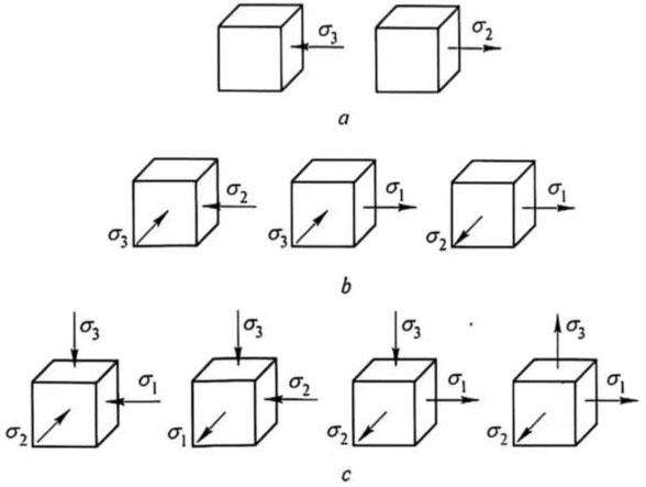
Figure 4 Principal stress diagram
a – Linear stress state; b – Plane stress state; c – Volume stress state
Principal deformation diagram: Plastic deformation is often represented using a principal deformation diagram. The principal deformation diagram provides a graphical representation of the presence and signs of principal deformations at the point of study (see Figure 5).
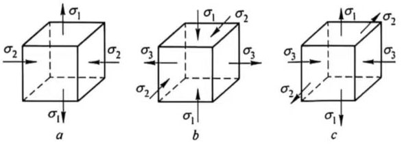
Figure 5 Principal Deformation Diagram
The effect of the principal stress diagram on the plasticity of deformed metals can be qualitatively described as follows: compressive stresses are more plastic than tensile stresses, and the closer to a triaxial compressive stress state, the greater the plasticity. Conversely, the greater the number of tensile stresses in the principal stress diagram, the greater the decrease in plasticity, i.e., the plasticity is minimized under a triaxial tensile stress state.
The effect of the principal stress diagram on deformation resistance can be qualitatively described as follows: principal stress diagrams with the same sign increase deformation resistance, while principal stress diagrams with opposite signs decrease deformation resistance.
The effect of the principal deformation diagram on the plasticity of an object can be qualitatively described as follows: a principal deformation diagram with two-way compression and one-way extension best utilizes the object’s plasticity, while a principal deformation diagram with two-way extension and one-way compression does not. In capacitors Production, understanding the principal deformation diagram helps optimize the rolling and forming processes of metal electrodes, thereby improving the mechanical properties and stability of the electrode material.
2.2 Conditions for Plastic Deformation
The transition from elastic deformation to plastic deformation (yielding) in a metal depends on the metal’s mechanical properties and the stress state it is subjected to. For example, during uniaxial tension (or compression), plastic deformation occurs when the tensile stress reaches the yield limit σs of the metal’s mechanical properties. Similarly, when twisting a thin-walled tube (pure shear), plastic deformation occurs when the shear stress reaches the shear yield strength of the object.
During press working, what relationship must be established between the stress components under complex stress states and simple stress states (uniaxial stress and pure shear stress) and experimentally determined σs and k to cause the metal to transition from elastic deformation to plastic deformation?
2.1.1 Maximum Shear Stress Theory
This theory assumes that for the same metal under the same conditions, whether in a simple or complex stress state, yielding occurs, i.e., the onset of plastic deformation, as soon as the stress state reaches its limit. The shear stress caused by it (see Figure 6) is:
![]() (4)
(4)
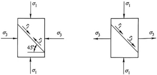
Figure 6 Relationship between principal stress and shear stress
2.1.2 Maximum deformation energy constant theory
The deformation energy constant theory believes that plastic deformation begins when the unit energy of changing the shape of an object reaches a limit value and this limit value is independent of the stress state of the object. The mathematical expression of the yield condition of this theory is:
![]() (5)
(5)
According to the deformation energy constant theory, the yield condition is:
![]() (6)
(6)
This formula takes into account the external conditions more comprehensively and is more in line with the actual deformation conditions. In capacitors Production, it can be used to evaluate the plastic performance of metal electrode materials under multi-directional stress.
2.3 Plastic deformation mechanism
Metals are generally polycrystalline composed of many single crystals or grains. To understand the plastic deformation of polycrystalline, you must first understand the plastic deformation of single crystals. The deformation mechanism of single crystals has the following two cases. (1) Slip. Under the action of an external force, one part of a crystal slides relative to another part along a specific crystal plane and direction. This crystal plane is called a slip plane, and this crystal direction is called a slip direction (see Figure 7). An example of slip deformation in a zinc single crystal is shown in Figure 8.
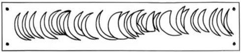
Figure 7 Schematic diagram of crystal slip
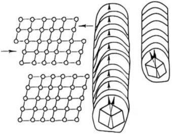
Figure 8 Stretched zinc single crystal at 300°C
Slip deformation generally occurs along the crystal plane and direction with the highest atomic density. The product of the slip plane and the slip direction is the slip system. The crystal structures of metals mainly include face-centered cubic lattice (such as copper, aluminum, silver, nickel, etc.), with slip planes {111}, slip directions <110), and slip system 12; body-centered cubic lattice (such as iron, chromium, molybdenum, tungsten, etc.), with slip planes {110}, slip directions <111>, and slip system 12; close-packed hexagonal lattice (such as zinc, cadmium, manganese, etc.), with slip planes {1000}, slip directions <1120>, and slip system 3 (see Figure 9).
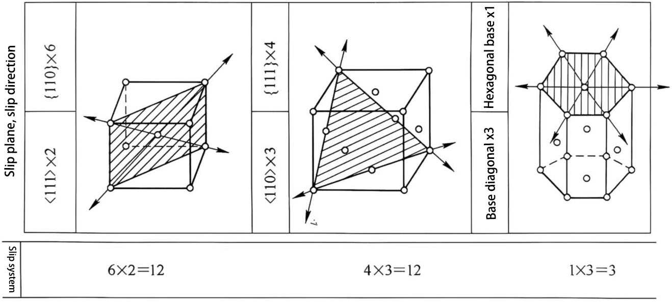
Figure 9 Main slip planes, slip directions, and slip
systems of metals When a crystal undergoes plastic deformation, it slips along two sets of crystal planes at the same time, which is called double slip. As a result, the slip lines are arranged crosswise, thereby increasing the sliding resistance (see Figure 10).
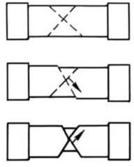
Figure 10 Schematic diagram of double slip in a single crystal
(2) Twins. Under shear stress, a portion of a crystal undergoes relative positional displacement along a specific crystal plane and orientation, resulting in a portion of the crystal being symmetrically positioned relative to the original crystal (see Figure 11).
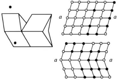
Figure 11: Schematic diagram of crystal twinning
Figure 12 compares the lattice distribution and displacement patterns of twinning and slip deformation.
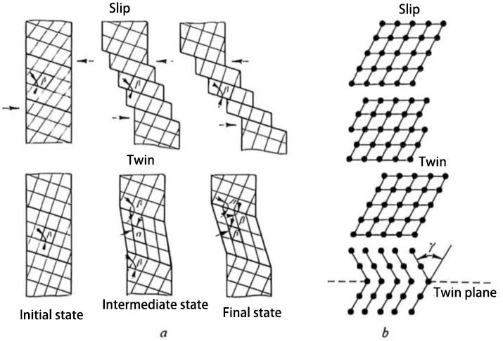
Figure 12: Schematic diagram of slip and twinning deformation
a: Shape change; b: Crystal node deformation
Twinning deformation is relatively rare in face-centered cubic (FCC) lattices and occurs primarily during high-speed deformation or low-temperature tensile deformation of body-centered cubic (BCC) metals.
In capacitors Production, understanding the mechanisms of double slip and twinning helps optimize the rolling and forming processes of metal electrode materials. If metal deformation involves slip across the entire atomic plane, the yield strength is much higher than the yield strength or deformation resistance exhibited in production. In reality, the metal deformation process involves a continuous process of dislocation movement and accumulation, significantly reducing the metal’s deformation energy.