1 capacitor casting dendrite structure
During the casting process, crystals always grow in the form of dendrites, which easily form a cellular structure with strong directionality or a more obvious dendrite network structure. This phenomenon is particularly significant in the capacitor casting dendrite structure. When the electromagnetic field is introduced during casting, the cellular structure or dendrite network structure disappears or is significantly improved (see Figure 1). Specifically, it is manifested as follows:
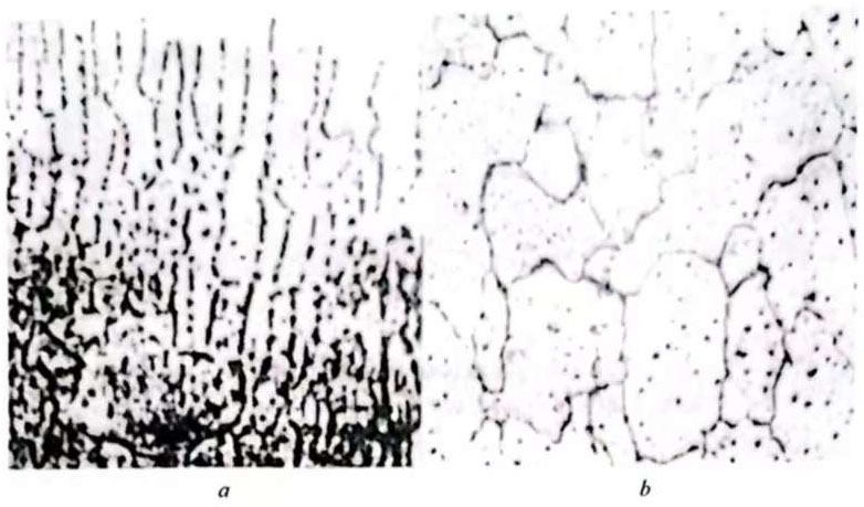
Figure 1 High-magnification structure under different casting conditions (x250)
a-blank sample without magnetic field; b-sample with electromagnetic field
(1) Improving the temperature field, that is, changing the temperature gradient to refine the dendrite network. The temperature gradient of the crystallization front is divided into three forms as shown in Figure 2: a, b, and c. Figure 2 a is a positive temperature gradient, that is, the farther away from the crystallization plane, the higher the temperature. The temperature of the crystallization plane is the melting point (solidification point) of the crystal. The temperature of the crystallization front is always higher than the melting point temperature of the product, which is an overheated melt. If there is an accidental disturbance for some reason, the solid-liquid interface forms a flange extending into the melt. Since the temperature in front of the solid-liquid interface is higher than the melting point of the crystal, it will melt immediately and return to a planar state, and will not form a cellular structure. Figure 2b shows a negative temperature gradient, which is an undercooled melt. The melt temperature in front of the solid-liquid interface is lower than the melting point of the crystal. Therefore, the flange generated by a certain disturbance is at a lower temperature at the tip and grows faster, grows into dendrites, and may form a developed dendrite network. The situation in Figure 2c is neither a single overheated melt nor a single undercooled melt, but there is a narrow undercooling zone in front of the solid-liquid interface. Therefore, the flange generated by interference in the undercooling zone can be preserved, but since the melt far away from the solid-liquid interface is still an overheated melt, these flanges cannot develop indefinitely, so they can maintain a stable size and grow into a certain cell block. Aluminum melt casting and rolling is carried out under such temperature conditions. If this narrow supercooling zone is reduced, the growth of the cell block can be limited or eliminated, and the development of the dendrite network can be controlled. After the electromagnetic field is introduced at the front of the casting and rolling crystallization, the strong electromagnetic stirring not only increases the “external” core and spontaneous nucleation of the melt, but also changes the temperature field at the front of the crystallization, reduces the depth of the liquid cavity of the casting and rolling, and increases the angle between the crystallization fibers. As shown in Figure 3, the angle without the application of the electromagnetic field is 20°~22°, and the angle with the application of the electromagnetic field is 30°~38°. It can be seen from the figure that the application of the electromagnetic field effectively reduces the supercooling zone, thereby improving or refining the dendrite network structure in the capacitor casting dendrite structure.
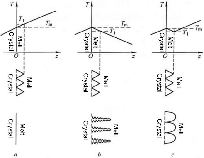
Figure 2 The influence of the temperature gradient morphology at the front of the crystallization on the crystallization structure
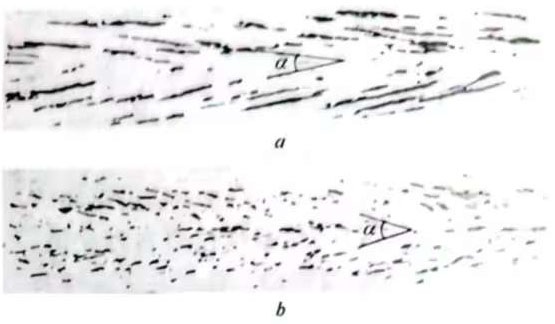
Figure 3 Low organization of the longitudinal section of the strip: comparison of the angle between the crystallization fibers a-no electromagnetic field; b-applied electromagnetic field
(2) Improve the supercooling conditions of the components and refine the dendrite network. In aluminum alloy casting and rolling, aluminum is the solvent, and other alloying elements and impurities are solutes. If the equilibrium distribution coefficient of the solute K0≠1, a solute boundary layer is formed at the front of the solid-liquid interface (see Figure 4). During the crystallization process, due to the different concentrations of the solute at each point in the boundary layer, the freezing points at each point are different, forming a component supercooling zone (see Figure 5).
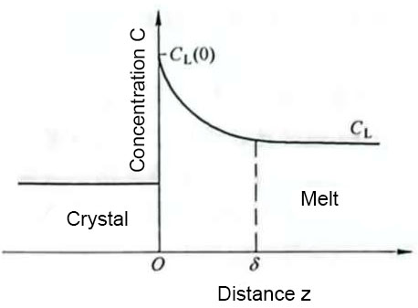
Figure 4 Solute distribution at the liquid interface (solute boundary layer)
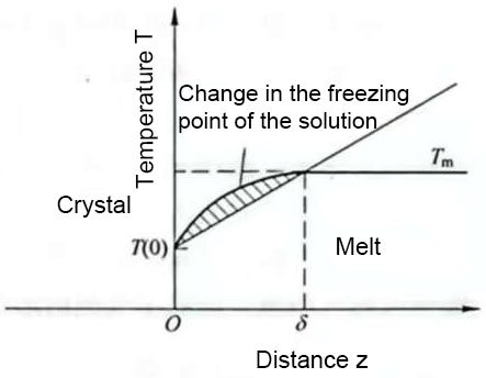
Figure 5 Solution freezing point distribution and component supercooling zone
In the mechanism where the solute transport is only diffusion, the component supercooling condition can be expressed as:
![]() (1)
(1)
In the formula, m – the slope of the liquidus line;
C0– the average concentration of the solute in the solution;
D – the diffusion coefficient of the solute;
v – the growth rate of the crystal;
G – the temperature gradient.
For a certain solution transmission system, the right side of equation 1 is a constant. If the growth rate increases, the ![]() value becomes smaller. When the
value becomes smaller. When the ![]() value decreases to a value less than the constant value on the right, that is, when equation 1 is established, component supercooling will occur, and cellular crystal structure or cellular dendrite structure (see Figure 6) may be generated, making the mechanical properties of the strip have strong directionality. This process is closely related to the formation of dendrite morphology in capacitor casting dendrite structure.
value decreases to a value less than the constant value on the right, that is, when equation 1 is established, component supercooling will occur, and cellular crystal structure or cellular dendrite structure (see Figure 6) may be generated, making the mechanical properties of the strip have strong directionality. This process is closely related to the formation of dendrite morphology in capacitor casting dendrite structure.
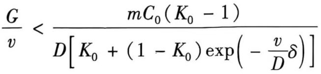
In electromagnetic casting and rolling, the stirring effect of the melt at the solidification front is increased, and the solute transmission is not only self-diffusion, but also forced convection transmission. When there is forced convection transmission, the condition for component supercooling is:
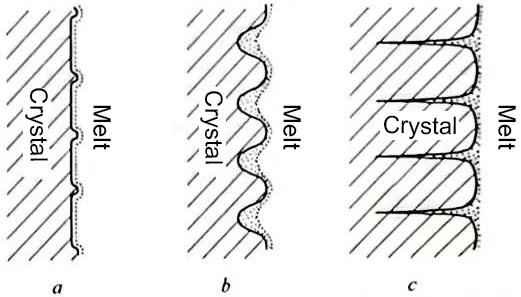
Figure 6 Formation process of cellular structure
 (2)
(2)
In the formula, δ is the thickness of the solute boundary layer.
Electromagnetic stirring greatly increases the diffusion coefficient and reduces δ. For a certain solution system, the right side of formula 2 is still a constant, but this constant is greatly reduced. If the crystal growth rate remains unchanged, that is, the cooling intensity of the casting and rolling is not increased and the casting and rolling speed is not changed, then the left side of formula 2 must be greater than the right side, so that the components will not be overcooled and cellular structures will not be generated.
2 Improve surface quality
The electromagnetic field used in casting and rolling is generally a composite magnetic field that combines pulse vibration and traveling wave. Since the magnetic field is always in a left-right running state, it provides favorable conditions for improving surface quality and optimizing capacitor casting dendrite structure.
In casting and rolling, defects such as horseshoe cracks, pass rod grooves, pass rod small cracks, and airways are often seen. After the electromagnetic field is introduced during casting and rolling, the stirring effect of the electromagnetic field to the left and right reduces the supercooling zone, shortens the liquid cavity depth, and refines the grain structure, thereby eliminating or greatly reducing the probability of horseshoe cracks, and obtaining a smooth and bright plate surface; the metal oxide sediment in the casting nozzle is blocked or removed, and the pass rod grooves and pass rod small cracks are eliminated or greatly reduced; the bubble source in the casting nozzle is removed, the conditions for the formation of bubbles are eliminated, and the generation of airway defects is prevented.
3 Problems with electromagnetic casting and rolling
The main problems with electromagnetic casting and rolling are:
(1) Chassis vibration, resulting in oxide film folding, and even possible melt leakage. Adding a low-frequency electromagnetic field may cause chassis vibration, resulting in oxide film folding on the surface of the cast and rolled plate and strip (see Figure 7). When the vibration is severe, it may even damage the casting nozzle and cause melt leakage.
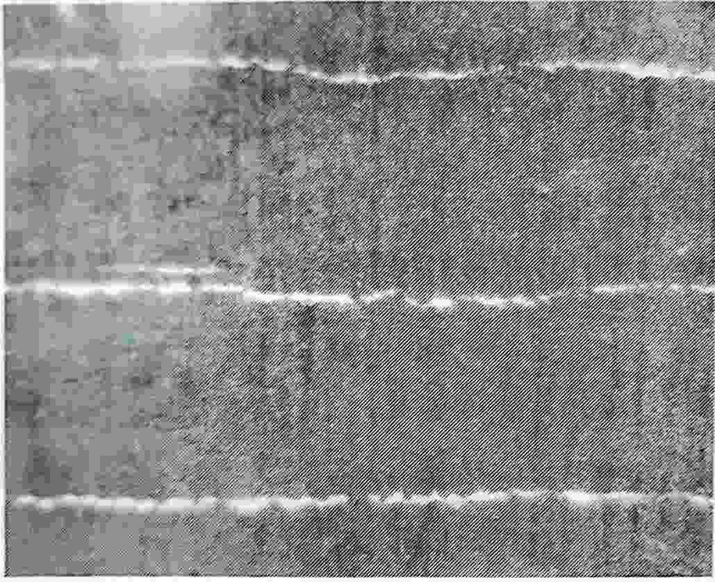
Figure 7 Oxide film folding pattern of cast and rolled strip
There are two reasons for the vibration of the system: one is that the manufacturing accuracy of the device is low, there is a gap between the magnetic conductors, and the attraction and desorption produce impact. The manufacturing accuracy should be improved to prevent impact during attraction: the other is that the casting and rolling parameters are improperly selected, resulting in the chassis’s inherent vibration frequency, the vibration frequency generated by the casting and rolling, and the electromagnetic oscillation frequency being basically the same or similar, causing resonance, which makes The vibration intensifies, destroying the normal gap between the nozzle and roller, or damaging the casting nozzle, forcing the casting and rolling to stop. Therefore, the natural vibration frequency of the chassis should be designed to be ≤3Hz, ≥20Hz.
(2) The addition of electromagnetic field can easily cause damage to the nozzle ear. The electromagnetic traveling magnetic field drives the melt to reciprocate in the casting and rolling area, and the melt impacts the ear. Over time, the ear material is relatively soft and cannot withstand the erosion of aluminum water, causing damage. A layer of graphite block or artificial mica is attached to the inside of the ear. Both graphite and mica have high strength and are resistant to aluminum water erosion, which can extend their service life. These measures also help to ensure the stability of the capacitor casting dendrite structure and casting quality.