🪐1. Failure of normal use
The failure of film capacitors can be the failure of normal use, and the probability of such failure is extremely low, and generally small batch applications may not be considered.
Except for the very low probability of failure in normal use, the most common failures of film capacitors are caused by improper application, such as overvoltage, overcurrent, and overheating.
🪐2. Overvoltage failure
(1). The main reason for the failure of film capacitors due to overvoltage: The probability of failure due to overvoltage increases, and the probability of failure increases by an order of magnitude for every 50K increase in temperature.
(2). Failure due to dielectric breakdown due to overvoltage: the main reason is that the actual rated voltage of the capacitor does not match the nominal voltage of the capacitor. For example, change a capacitor with a rated voltage of 400V to a capacitor with a rated voltage of 630V. Since the test voltage of the film capacitor is generally 1.7 times the rated voltage, and the dielectric strength is higher than the test voltage, it is generally not a problem to use a film capacitor with a rated voltage of 400V as a 630V film capacitor, unless the capacitor’s dielectric strength is tested before application. Electric strength, then divide this value by 2~2.5 to get the rated voltage of the capacitor.
(3) The most common overvoltage failure may be the failure of the film capacitor due to the overvoltage occurring in an abnormal state. The situation may occur when the electronic ballast is working in an abnormal state, the overvoltage generated on the ignition capacitor; the ordinary capacitor as a power supply electromagnetic interference suppression capacitor will cause the capacitor to fail when the power supply voltage has a severe overvoltage or surge voltage.
For the ignition capacitor of the electronic ballast, in the normal working mode, the ignition capacitor only bears the ignition voltage of the lamp within a short period of time when the lamp is ignited. If it is preheating, the peak voltage of the device will not be higher than 630V. However, when the fluorescent tube cannot be ignited and the filament is not broken, the ignition capacitor will resonate with the ballast inductance to generate a high-amplitude resonant voltage, which can easily exceed 1000V. Under the conditions of both high temperature and high frequency, the overvoltage breakdown of thin film electrical appliances can be achieved within a few minutes.
If general-purpose film capacitors are used as capacitors for suppressing electromagnetic interference of power supplies, they cannot pass the instantaneous overvoltage and surge voltage tests in the form of electromagnetic compatibility experiments. Even if the form of electromagnetic compatibility experiment is not carried out, in actual operation, it may fail due to the accidental surge voltage or instantaneous overvoltage in the power grid.
🪐3. Overheating failure when the ambient temperature is too high
From the relationship between the failure rate and the temperature and the relationship between the rated voltage and the temperature, it can be known that an excessively high ambient temperature will lead to an increase in the failure rate of the film capacitor. Because the temperature is too high, the organic dielectric film of the capacitor can be softened or even melted, and the insulation performance will be deteriorated at the same time.
For paper dielectric capacitors, boiling of the immersed capacitor oil or carbonization of the capacitor paper may result in the failure of the paper dielectric capacitor. Even if the temperature does not reach the temperature at which the capacitor oil boils or the capacitor paper is carbonized, an excessively high temperature will increase the capacitor oil Evaporation rate, resulting in a decrease in the capacitance and dielectric strength of the paper dielectric capacitor, leading to failure.
As the temperature increases, the insulation resistance of the medium decreases, which increases the leakage current and increases the probability of capacitor failure.
🪐4. Overheating failure due to overcurrent
Failure due to overcurrent and overheating is a common failure mode for film capacitors. The reason for this failure mode is that due to the limited effective area of the electrode of the film capacitor, the equivalent series resistance of the electrode cannot be ignored. When an excessively high current flows through the capacitor, the excessively high current generates a relatively large loss in the equivalent series resistance of the electrode and causes excessive heating, which in turn causes the film capacitor to enter an overheating failure mode, which causes the film capacitor to fail. The reasons for this phenomenon are:
(1). Most of it is caused by improper selection of capacitors. For example, the “breakthrough” absorption capacitors in switching power supplies or frequency converters choose general-purpose capacitors, and the resonance capacitors of power resonant circuits choose general-purpose capacitors to generate high power. The bypass of the circuit ripple current circuit uses general purpose capacitors, etc.
(2). The circuit entering an abnormal working state can also cause the capacitor to overcurrent and overheat. For example, when the excessive harmonic current in the power grid flows into the power factor compensation capacitor, it will compensate the capacitor overcurrent and overheat; the fluorescent lamp cannot start, so that the electronic ballast enters the ballast inductance and the ignition capacitor in series resonance, and the flow rate The normal current is much larger than the resonant current, which causes the capacitor to overcurrent and overheat. In resin-encapsulated capacitors, this failure can be seen to cause the resin-encapsulated capacitor to explode at the terminal.
.In the design, due to insufficient pre-estimation, the current of the capacitor in the actual circuit is higher than the rated current of the capacitor, resulting in overheating failure due to excessive current.
🪐5. Overcurrent failure due to rapid discharge
Although in theory the capacitor can be short-circuited and discharged, in practice, due to the limited current-carrying capacity of the capacitor electrode, it is not allowed to charge or discharge with a very high current value, especially the circuit discharge. The reason is that when a sharply discharged high-amplitude current flows through the entire conductive part of the capacitor, it will cause the weakest part of the conductive capacity to blow like a fuse. The part between the electrode of the capacitor and the terminal is the weakest part of the capacitor’s sharp discharge. Therefore, in this type of failure, the part between the electrode and the terminal is often damaged.
The replacement of the capacitor in the camera flash with a general-purpose electrolytic capacitor will also cause the internal lead to be burned or other types of failure due to the rapid discharge current.
Therefore, in applications requiring rapid discharge of the capacitor, the capacitor should be a “pulse” capacitor dedicated to rapid discharge. Such capacitors allow peak discharge currents of up to 10,000A or even higher.
🪐6. Too high dv/dt overcurrent failure
From the relationship between capacitor voltage and current:
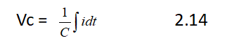
Can get:
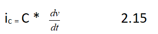
The following phenomena may occur:
(1). In the frequency converter, the rate of change of the Vce of the IGBT during the turn-off process can reach a voltage change rate of hundreds of volts or even thousands of volts per microsecond. If the snubber capacitor connected to the collector and emitter of the IGBT has a capacitance of 1μF, the current peak value will reach hundreds or even thousands of amperes [A]. From this result, it can be seen that the snubber capacitor of the IGBT must be able to withstand the very peak current impact.
(2) Such a high rate of voltage change will also occur in the buffer circuit of the switching power supply switch tube. For example, a 1000pF buffer capacitor has a voltage change of 1000V/μs during the switch-off process, and the corresponding peak current flowing through the capacitor is 1A.
(3) The snubber capacitor of the thyristor inverter also has the problem of high peak current impact. If the snubber capacitor is replaced with a general-purpose capacitor, the snubber capacitor will be damaged due to overheating after a short operating time.
🪐7. Failure of improper mechanical stress
Improper mechanical stress is a common phenomenon of capacitor damage. For example, if the length of the pins of the capacitor inserted on the circuit board is too short, the capacitor pins will be improperly stressed due to thermal expansion and contraction. In the long run, the capacitor pins and capacitor ends will break and become invalid. Therefore, the pins of many capacitors are deliberately bent at the roots when they leave the factory to reduce improper application of force.
In terms of the assembly of the capacitor, the stress of the capacitor pin when inserted into the via hole of the circuit board should be as small as possible, and the method of pre-bending the leg to a suitable size can be used.
🪐8. Low-level failure mechanism of high-frequency precision capacitors
Among many organic film capacitors, polystyrene film capacitors have the advantages of low loss, large insulation resistance, good stability, and high dielectric strength. Precision polystyrene capacitors can be used in high-frequency circuits instead of mica capacitors. It should be noted that precision polystyrene capacitors used in high-frequency circuits generally use metal foil plates to improve insulation resistance and reduce losses.
Low-level failure of capacitors is a new problem that has emerged since the 1960s. Low-level failure refers to the failure of capacitors such as open circuit of capacitors or excessive drop in capacity under low voltage working conditions. Since the 1960s, semiconductor devices have been widely used. The voltage of semiconductor circuits is much lower than that of electronic tube circuits. The actual working voltage of capacitors is only a few millivolts in some circuits. If the capacity is live or partly loses the capacity, with a low level impact, the capacity of the capacitor can be restored to normal.
The main reason for the low-level failure is that the lead wire of the capacitor is in poor contact with the capacitor plate, and the contact resistance increases, resulting in a complete open circuit of the capacitor or a decrease in capacitance.
Precision polystyrene film capacitors generally use aluminum foil as the pole plate, and the copper lead wire and the aluminum foil pole plate are spot welded together. Aluminum foil is easily oxidized in the air; a layer of aluminum oxide semiconductor film is formed on the surface of the electrode plate, and the voltage on the oxide film layer under low-level conditions is not enough to break it down, so the gap capacitance formed between the aluminum foils is equivalent in series The capacity, the gap capacitance is smaller, and the series equivalent capacity is also smaller. Therefore, the low-level capacity depends on the thickness of the aluminum oxide layer on the surface of the electrode plate. The thicker the aluminum oxide layer, the smaller the capacitance of the capacitor under low-level conditions. In addition, when the capacitor is working in an AC circuit, its effective capacitance will decrease due to excessive contact resistance. When the contact resistance is large, the effective capacitance can be reduced to the extent of an open circuit, even if there is no poor conduction gap between the plate and the lead. Layers, will also produce these consequences.
The specific factors that cause the low-level failure of precision polystyrene capacitors are summarized as follows:
(1). The lead surface is oxidized or the dip layer is too thin, so that the welding is not strong.
(2) The lead wire and the aluminum foil are poorly welded, and the aluminum oxide film layer at the spot weld on the surface of the aluminum foil is not eliminated.
(3) The number of solder joints of the single-lead structure is too small, which increases the probability of low-level failure.
(4) Although the contact area of the flattened part at the root of the thick lead is larger, the stress at the solder joint after spot welding is also larger. During the heat treatment or temperature cycle, the contact part may be damaged and the contact condition may be deteriorated.
(5) Moisture enters the capacitor core, oxidizes and corrodes the solder joints, and increases the contact resistance.
The specific factors that cause the low-level failure of mica capacitors are summarized as follows:
(1). There is a thin layer of ground wax film between the silver electrode and the copper foil, and between the copper foil and the lead card. Under low-level conditions, the applied voltage is not enough to break down the insulating film, resulting in gap capacitance , And increase the contact resistance.
(2). The silver electrode and copper foil are corroded by harmful gases, which increase the contact resistance. In a humid sulfur environment, silver and copper are easily vulcanized, which increases the contact resistance between the electrode plate and the lead.
🪐9. Failure mechanism of metallized paper capacitor
The electrode plate of a metalized paper capacitor is a metal film that is vacuum evaporated on the surface of the capacitor paper. Due to the extremely thin thickness of the metalized film, a point parameter deterioration and failure may occur in the metalized film capacitor, and lead breaks and failures may occur.
(1). Deterioration of electrical parameters and failure. “Self-healing” is a unique advantage of metallized capacitors, but the self-healing process is quite complicated. Although self-healing can prevent the capacitor from breaking down due to dielectric short-circuit, the self-healing part will definitely cause metal particle migration and thermal cracking of the dielectric material. The phenomenon. Capacitor paper is composed of fibers, and cellulose is a high molecular weight substance of carbohydrates. At high temperatures, the capacitor cellulose decomposes into free carbon atoms or carbon ions, which increases the surface conductivity of the self-healing part, resulting in a decrease in the resistance of the capacitor, an increase in loss and a decrease in capacitance. In severe cases, the capacitor may become invalid due to the deterioration of the electrical parameters exceeding the allowable range of the technical conditions.
When metallized paper dielectric capacitors work below the rated operating voltage, the self-healing energy is insufficient, and the conductive impurities stored in the capacitor paper form a low-resistance path under the action of the electric field, which can also cause the capacitor’s insulation resistance to decrease and the loss to increase .
Capacitor paper is a porous polar organic dielectric material that easily absorbs moisture. Although the capacitor core has been immersed, if the process is improper or impure, or immersion aging occurs after a long period of work under the action of an electric field, the insulation resistance of the capacitor will be reduced and the loss will therefore increase.
Capacitance out-of-tolerance failure is a failure form of metallized paper capacitors. Metallized paper capacitors may fail due to excessive increase in capacitance when stored under high temperature conditions, and may fail due to excessive decrease in capacitance when operating under high temperature conditions. Semi-hermetic metallized paper dielectric capacitors will inevitably absorb moisture when stored at high temperatures. Water is a strong polar substance, and its dielectric constant is close to 20 times the dielectric constant of an impregnated capacitor. Therefore, a small amount of moisture invades the capacitor core, which will also cause a significant increase in capacitance. The electric capacity will decrease after baking and dehumidification. If the capacitor works in a high-temperature environment, the combined action of moisture and electric field will cause electrolytic corrosion of the metal film electrode, reducing the effective area of the electrode plate and increasing the resistance of the electrode plate, resulting in a substantial decrease in capacitance. If corrosion occurs at the contact part of the lead wire and the metal film layer, the contact resistance will increase and the effective capacitance of the capacitor will be further reduced. The capacitance of individual capacitors can be reduced to close to an open circuit.
(2) The lead breaks and fails. When metallized paper capacitors work in a high-humidity environment, the root of the positive terminal lead of the capacitor will be severely corroded. This electrolytic corrosion leads to a decrease in the mechanical strength of the lead, and in severe cases, the lead may break and fail.