During metal deformation, the deformation is non-uniform, and stress and residual stress exist within the deformed body. The core objective of all technical work in the rolling process of capacitor plate strips is to achieve uniform deformation of the rolled product as much as possible, eliminate the adverse effects of non-uniform deformation, and reduce residual stress. However, regardless of the measures taken, non-uniform deformation always exists, and the first problem it brings is defects in the strip shape.
1 Capacitor Plate Strips Shape
The term “strip shape” intuitively refers to the flatness or degree of warpage of the strip surface; in essence, it refers to the distribution of residual stress within the strip. This indicator is also an important evaluation criterion in the quality control of XUANSN capacitor plate strips.
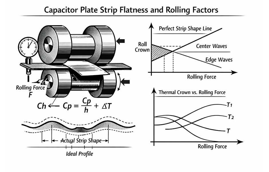
A major requirement for the rolling process of strip materials is uniform longitudinal elongation across the width of the strip. This requirement is particularly crucial in the rolling of capacitor plate strips. However, the rolling process is a complex physical change process. Under the action of rotating elastic bodies—the rolls—the metal undergoes significant longitudinal elongation and a certain degree of lateral flow (including widening), and the plastic deformation of the metal is non-uniform (see Figures 1 and 2). The existence of non-uniform deformation means that there are residual internal stresses within the metal. If this internal stress is insufficient to cause a change in the flatness or warpage of the strip surface, it is called potential strip shape defect; if the stress is large enough to cause the strip to warp, it is called apparent strip shape defect.
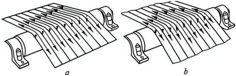
Figure 1 Straight strip (a) and non-straight strip (b)
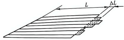
Figure 2 Schematic diagram of a non-straight strip after cutting and straightening
2 Mechanical Conditions for Strip Warping
According to the research results of elasticity mechanics, the mechanical conditions for strip warping can be expressed as:
![]() (1)
(1)
Where σa is the critical stress for strip warping;
B is the strip width;
h is the strip thickness;
Ep, vp are the Young’s modulus and Poisson’s ratio of the strip;
kcr is the critical stress coefficient for strip warping.
The critical stress coefficient kcr for strip warping depends on the stress distribution characteristics and the support conditions at the edges of the plate, and it can vary by orders of magnitude.
3 Plate Shape Representation Methods
There are many methods for representing plate shape, including relative length difference representation, waveform representation, vector representation, residual stress representation, polynomial representation of the strip cross-sectional shape, and relative thickness change representation. Here, only the commonly used relative length difference representation and waveform representation are introduced.
3.1 Relative Length Difference Representation
Figure 3a shows the shape of a rolled material after warping. This rolled piece has severe edge waves due to significant elongation at the edges. This phenomenon is particularly typical in the rolling process of capacitor plate strips. When the strip is cut into several longitudinal strips and flattened, as shown in Figure 3b, the different elongations at different points in the transverse direction can be clearly seen. The relative length difference ΔL/L at different points in the transverse direction is used to represent the plate shape. L is the length after rolling at the chosen reference point; ΔL is the difference in length after rolling at other points relative to the reference point. The relative length difference is also called the plate shape index ρ, ρ = ΔL/L.
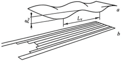
Figure 3 Warped plate (a) and its segmentation (b)
Alcan (Aluminum Company of Canada) uses the relative length difference between the longest and shortest longitudinal strips in the transverse direction as the unit of plate shape, called the I unit. One I unit is equivalent to a relative length difference of 10-5. Therefore, the plate shape Σst is:
![]() (2)
(2)
Typical plate shape tolerances for aluminum plates are shown in Table 1.
Table 1 Typical Plate Shape Tolerances for Aluminum Plates
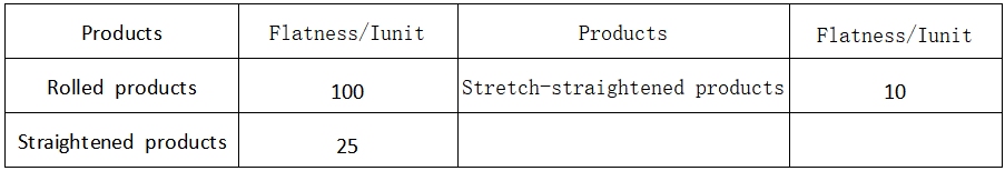
Decorative strips and high-grade PS plate aluminum substrates require tolerances less than 3I, indicating that general rolling and stretch-straightening products are far from meeting the requirements.
3.2 Waveform Representation
A section of the strip is cut and placed on a platform. If the shortest longitudinal strip is considered a straight line and the longest longitudinal strip is considered a sine wave (see Figure 4), the warpage λ of the strip can be expressed as:
![]() (3)
(3)
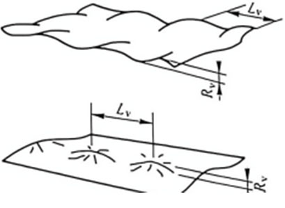
Figure 4 Two plate shape situations of strip warpage
Where Rv – amplitude;
Lv – wavelength.
This method is intuitive and easy to measure. Currently, most manufacturing enterprises in my country use this method to measure and represent plate shape.
Let the length of the curved part corresponding to the straight line of length Lv in Figure 5 be Lv + ΔLv, and assume that the curve changes according to a sinusoidal law. The relative length difference between the curved part and the straight part can be calculated using a line integral.
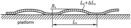
Figure 5 Waveform curve of a sine wave
Assuming the waveform curve is a sine wave, the length of the curve corresponding to Lv is:
![]() (3-1)
(3-1)
Therefore, the relative length difference between the curved part and the straight part is:
![]() (4)
(4)
Equation 4 shows the relationship between the warpage λ and the relative length difference between the longest and shortest longitudinal strips. This relationship indicates that in the evaluation of the plate shape of capacitor plate strips, the strip waveform can be used as an equivalent representation of the relative length difference; as long as the waveform parameters of the strip are measured, the relative length difference can be calculated accordingly, thus achieving quantitative evaluation of the plate shape.