What to Consider When Choosing a Capacitor
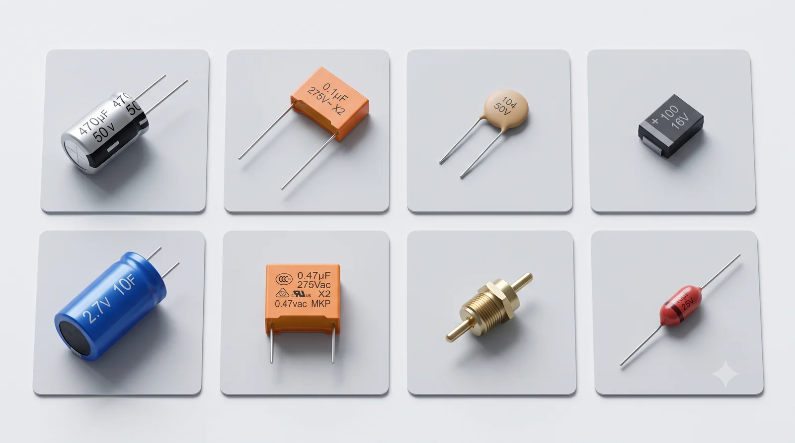
Choosing the right capacitor is about matching real circuit requirements — capacitance, voltage, ESR, temperature and frequency — not just reading nominal values. A capacitor that works in one role may fail in another: an aluminum electrolytic that smooths a power rail is the wrong choice for a high-frequency decoupling point, and a ceramic part selected for capacitance may deliver far less than marked once DC bias is applied. This guide walks through the selection steps and the common mistakes to avoid. For a full comparison of capacitor types, see our complete capacitor types guide.
Step 1: Define the Application
The circuit role decides the capacitor family. Capacitance, voltage and ESR targets all follow from what the capacitor must do:
| Application | Recommended Type | Why |
|---|---|---|
| Decoupling / bypass | MLCC (X7R/X5R) | Low ESR and high-frequency performance |
| Bulk power smoothing | Aluminum electrolytic or polymer | High capacitance, cost-effective |
| Timing / oscillator / precision filter | C0G/NP0 ceramic or film | Value must not drift with voltage or temperature |
| Audio coupling | Film (PP/PET) | Stable, linear, no DC-bias distortion |
| AC mains / safety | X/Y safety film | Fail-safe, agency-rated |
| Snubber / pulse | Film (PP) | Handles fast dV/dt and pulse current |
Step 2: Choose the Capacitance
Capacitance sets the energy and charge the part can store. Power-supply filters need large values in the µF to mF range, signal coupling uses nF to µF, and precision filters need exact pF values. Two cautions apply: always account for tolerance, and for Class II ceramics (X7R/X5R) check the DC bias curve — an X7R MLCC rated 10 µF may deliver only 3–4 µF at its rated voltage because capacitance falls as DC voltage rises. Oversize Class II ceramics by 2–3× if you need a guaranteed value.
Step 3: Voltage Rating and Derating
Never exceed the rated voltage, even transiently. Apply a safety margin and follow technology-specific derating rules:
- General rule: at least 1.5–2× the expected operating voltage.
- Aluminum electrolytic: operate at or below 80% of the rated DC voltage; ripple voltage adds to the DC level.
- Tantalum: derate to about 50% of rated voltage in reliability-sensitive designs, because tantalum capacitors can fail short and ignite under overvoltage.
- Ceramic: a higher voltage rating also recovers capacitance lost to DC bias effects.
Step 4: ESR and Ripple Current
ESR is the capacitor’s internal resistance that produces heat and energy loss. Ripple current flowing through ESR causes I²R heating; exceeding the ripple current rating shortens life or causes thermal runaway.
- Low ESR (ceramic, polymer, film) means low ripple voltage and cool operation under high ripple — essential for switching supplies.
- Higher ESR (standard aluminum electrolytic) is acceptable for bulk hold-up but self-heats under heavy ripple.
- Very low ESR is not always better: in some audio and analog circuits, too-low ESR can cause oscillation.
Step 5: Temperature and Tolerance
Match the operating temperature range to the environment and consider how capacitance drifts with temperature. C0G/NP0 ceramic has a near-zero temperature coefficient, while X7R drifts roughly ±15%. For timing and precision circuits, choose a type whose value stays stable across temperature rather than relying on an average.
Step 6: Frequency and Self-Resonant Frequency
Every capacitor behaves inductively above its self-resonant frequency (SRF), so it stops being a capacitor at high frequency. Smaller packages have lower inductance and higher SRF. For broadband decoupling, several small capacitors in parallel often outperform one large capacitor.
Capacitor Selection by Application
Once the application is clear, pick the family and verify the parameters against the circuit conditions. For power supplies, combine an aluminum electrolytic for bulk energy with ceramics for high-frequency noise. For precision and audio, choose film or C0G. For AC mains, use only safety-certified X/Y capacitors. For high dV/dt and pulse circuits, use film snubber capacitors rated for the pulse current.
Capacitor Selection Process: 6 Steps
- Define the application and the capacitor family it needs.
- Size the capacitance, accounting for DC-bias loss and tolerance.
- Choose the voltage rating with the correct derating for the technology.
- Verify ESR and ripple current against the circuit conditions.
- Check temperature stability and tolerance for precision roles.
- Validate with manufacturer curves and datasheets before layout.
Practical Tips for Different Circuits
For digital power rails, combine a bulk aluminum electrolytic with 100 nF MLCCs per power pin to cover low- and high-frequency decoupling. For analog audio paths, prefer film or C0G capacitors to avoid distortion. For high-speed digital interfaces, use small-package MLCCs with high self-resonant frequency placed close to the pins. For mains-connected equipment, always use safety-certified X/Y capacitors rated for the line voltage.
Common Selection Mistakes
- Ignoring DC-bias derating on Class II MLCCs
- Using aluminum electrolytics for high-frequency decoupling
- Reversing polarity on polarized capacitors
- Under-derating tantalum capacitors
- Specifying only capacitance without checking ripple current and ESR
FAQ
What capacitance value do I need? It depends on the application — bulk power filtering uses µF to mF, coupling uses nF to µF, and precision circuits use exact pF values with a stable dielectric.
How much voltage margin should I leave? At least 1.5–2× the working voltage in general; follow the derating rule of the specific technology (electrolytic ≤80%, tantalum ≤50%).
Why does ESR matter? ESR generates heat from ripple current (P = I²R). Low ESR is needed for switching supplies; standard electrolytics have higher ESR but are fine for bulk hold-up.
Does capacitance drop under voltage? For Class II ceramics yes, sharply with DC bias; check the manufacturer’s DC bias curve and oversize if needed.
Can I use one large capacitor instead of several small ones? For broadband decoupling, several small capacitors in parallel usually outperform one large part because they extend the frequency range and lower overall ESR.
Are ceramic capacitors affected by DC voltage? Yes — Class II ceramics (X7R/X5R) lose a large share of their capacitance as DC voltage rises; always check the DC bias curve.
Are all capacitors polarized? No — aluminum electrolytic and tantalum capacitors are polarized and require correct polarity, while ceramic and film capacitors are non-polarized.
For a deeper look at one capacitor family, see our aluminum electrolytic capacitor selection guide.
Choosing a Capacitor Supplier
After you settle the type and parameters, qualify the supplier. Confirm the manufacturer operates its own factory, holds quality certifications such as ISO 9001, and can supply the exact type and voltage you need. Request datasheets and production samples, test them under your real circuit conditions, and agree on MOQ and lead time before scaling. For a full guide on qualifying a supplier, see our aluminum electrolytic capacitor manufacturer guide.
Need Help Choosing a Capacitor?
Xuansn Capacitor manufactures aluminum electrolytic, film, ceramic, solid and super capacitors. Tell us your application, voltage, capacitance and ripple requirements, and our engineers will recommend the right type — send your inquiry.