1.Factors Affecting the Plate Shape of Capacitor Plate Strip
Plate shape is a very complex issue, and many factors influence it. A change in any condition during the production process will cause a change in the plate shape of the capacitor plate strip. Before discussing the issue of plate shape changes, let’s introduce the concepts of plate crown, slab thickness, and their relationship to plate shape.
The plate crown referred to here is for the part excluding the edge thinning area. The edge thickness is represented by the thickness at a point near the edge but outside the edge thinning area. The plate crown is the difference between the thickness at the center of the plate and the thickness at the representative point at the edge of the plate.
The plate crown (sometimes called the central plate crown) is expressed as:
![]() (1)
(1)
The rolling thickness and plate shape and plate crown are closely related. Therefore, the concept of proportional crown is introduced. The proportional crown Cp is expressed as the ratio of the plate crown Ch to the average thickness h of the rolled product, i.e.:
![]() (2)
(2)
In the metal rolling process, the above good plate shape condition can be written as:
![]()
Plate crown is closely related to plate shape. Because the cold rolling process requires strict assurance of good plate shape for capacitor plate strip, although the absolute value of the plate crown continuously decreases during the rolling process, the proportional crown should always remain constant. To ensure good plate shape for decorative strips and PS plate aluminum substrates, the plate crown of the blank must be controlled within a reasonable range.
The metal undergoes a series of deformation processes under the action of the rolls to be rolled into the required plate and strip. The plate shape of the final product is affected by many factors, which can be broadly divided into two aspects: the inherent properties of the metal (internal factors) and the rolling conditions (external factors):
(1) The physical properties of the metal itself, such as the hardening characteristics and deformation resistance of the metal material, directly affect the magnitude of the rolling force and are closely related to the plate shape; the geometric characteristics of the metal workpiece, such as the width-to-thickness ratio of the plate and the plate crown of the raw material, are also important factors affecting the plate shape.
(2) The influence of rolling conditions is more complex and includes a wider range of factors. All factors that affect rolling pressure and roll crown, such as friction conditions, roll diameter, tension, rolling speed, bending force, and wear, as well as factors that can change the contact pressure distribution between the rolls, such as roll shape and initial roll crown, all affect the strip shape of capacitor plate strip.
2.Relationship between Rolling Force, Roll Crown, and Good Strip Shape Curve
Assuming that the initial strip crown and all process parameters remain constant, only the roll crown is adjusted to ensure a good strip shape. At this point, the elastic deformation of the rolls under the rolling force should be exactly balanced by the roll crown. Then, the rolling force is changed, and the roll crown is adjusted simultaneously so that the adjustment value of the roll crown exactly compensates for the change in elastic deformation of the rolls caused by the change in rolling force, thus maintaining a good strip shape for the capacitor plate strip. A curve is then plotted showing the relationship between the rolling force and the roll crown that results in a good strip shape. This curve is called the perfect strip shape line, as shown in Figure 1.
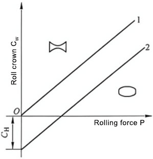
Figure 1 Perfect Strip Shape Line
1- Incoming strip crown is zero; 2- Incoming strip crown is CH
When the incoming strip crown is zero, the perfect strip shape line passes through the origin. When rolling in the area above the perfect strip shape line, the rolled product produces center waves; when rolling below the perfect strip shape line, the rolled product produces edge waves; only when the working point determined by the roll working crown and rolling force is on the perfect strip shape line will a good strip shape be obtained. Studies have shown that under actual rolling conditions, the perfect strip shape line is a straight line. This is because the elastic deflection of the rolls, which exhibits a linear relationship, plays a greater role in roll deformation than the elastic flattening of the rolls, which exhibits a non-linear relationship.
In actual production, the material itself generally has a certain crown CH. When producing decorative strips and medium- and high-grade PS plate substrates, the cast-rolled incoming material is generally required to have a positive crown of 0.2% to 0.7%. To satisfy the condition of good strip shape, the work roll profile should have a corresponding negative crown CH. The existence of this negative crown causes the ideal strip shape line to shift downwards by a certain distance, and its intersection with the y-axis has coordinates of -CH. Therefore, when the incoming material crown changes, the ideal strip shape line moves correspondingly upwards or downwards.
Of course, to obtain the ideal capacitor plate strip shape, the cross-section of the slab should be a strictly sinusoidal or parabolic shape, and should not exhibit a W-shape or wedge shape, i.e., the thickness of the strip gradually decreases as the distance from the center of the strip cross-section increases. However, in production practice, there are many factors that cause fluctuations in the casting and rolling process, and it is quite difficult to achieve this perfectly. The thickness of corresponding points at different widths of the cross-section also varies randomly and cannot be an ideal sinusoidal or parabolic shape. It may be a wavy line with small fluctuations between two ideal sinusoidal or parabolic curves (see Figure 2), with a certain amount of fluctuation, but the fluctuation amount is extremely small and should not exceed a reasonable allowable range. Generally, the fluctuation range of this value should not exceed ±5 μm.
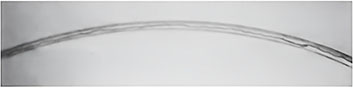
Figure 2 Schematic diagram of the allowable fluctuation range of thickness on the cross-section
3. Relationship curves of capacitor plate strip considering thermal convexity
During the rolling process, friction and relative sliding occur between the rolled material and the rolls, generating frictional heat, causing the rolls to expand due to heat, resulting in thermal crown. The value of the thermal crown is proportional to this heat. The heat generated by the relative sliding between the metal and the rolls is:
![]() (3)
(3)
Where P is the rolling force;
b1 is a constant.
Numerous simulation experiments have proven that a compression ratio y < 60% can satisfy the above relationship. The metal also generates a large amount of heat during deformation, but the contact time between the metal and the rolls during deformation is short, and the heat transferred to the rolls is very small. For the sake of simplification, it is ignored. Since the thermal crown is proportional to the heat, there is also a certain proportional relationship between the thermal crown and the rolling force, but the coefficient is not b1. The thermal crown-rolling force curve is shown in Figure 3.
XUANSN found in actual production that the initial roll crown has the greatest impact on the thermal crown. If the initial roll crown is positive, the curve shifts upwards; if it is negative, the curve shifts downwards. Hydraulic bending rolls actually provide the rolls with an initial crown using mechanical methods, and their effect is the same as that of the initial roll crown.
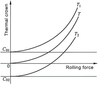
Figure 3. Thermal Crown-Rolling Force Curves at Different Initial Roll Crowns
T1 – Curve when initial roll crown C0 = C01 (C01 > 0); T – Curve when C0 = 0; T2 – Curve when C0 = C02 (C02 < 0)
The thermal crown is affected by many factors, the most important of which is the initial crown C0. When the roll has an initial crown, it is equivalent to superimposing a constant value on the original thermal crown curve, so the curve shifts. If the initial roll crown is positive, the curve shifts upward, as in T1; if the initial roll crown is negative, the curve shifts downward, as in T2.
Hydraulic bending rolls actually provide the rolls with an initial crown using mechanical methods. Its effect is the same as that of the initial roll crown; the curve shifts upward during positive bending and downward during negative bending.
4.Thermal Crown-Rolling Force Relationship Curve with Tension
The presence of tension, especially back tension, reduces the rolling force, which inevitably affects the thermal crown-rolling force curve. Theoretical analysis shows that changes in front and back tension have different effects on the thermal crown-rolling force relationship curve. As shown in Figure 4, back tension has a greater impact on the curve; when the back tension increases, the thermal crown increases, and the curve changes from T to T1; front tension has a smaller impact on the curve; when the front tension increases, the thermal crown decreases slightly, and the curve changes from T to T2.
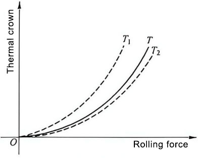
Figure 4. The Influence of Tension on the Thermal Crown-Rolling Force Relationship Curve
T – Tension is a certain value; T1 – Increased back tension; T2 – Increased front tension
The ideal strip shape line and the thermal crown-rolling force relationship curve are plotted on the same graph (see Figure 5), forming a process diagram, which reflects the influence of various process variables on the strip shape of capacitor plate strip. XUANSN indicates that in actual production, the ideal working conditions are rarely met exactly, and the operation is always in a region deviating from the ideal point; therefore, the strip shape may have certain defects. In regions I and III, the actual working crown of the roll is greater than the crown required for good strip shape, resulting in center waves; in region II, edge waves occur.
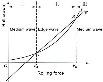
Figure 5 Process Diagram
III – Center Wave Region; II – Edge Wave Region
Under a certain initial roll crown and tension, the relationship between the actual working crown of the roll and the rolling force is represented by curve T. According to mechanical conditions, a good strip shape can only be obtained when the roll crown and rolling force satisfy the relationship represented by curve F. Curve T represents the actual situation, while curve F represents the ideal situation. When the rolling force takes the values PA and PB corresponding to the intersection points A and B of curves T and F, a good strip shape can be obtained. When deviating from these two points, strip shape defects will occur. In actual production, the probability of exactly meeting the ideal working conditions is very small; the process always operates within a certain region deviating from the ideal point. Therefore, the strip shape is not the ideal “flat” shape, but rather a shape with certain defects. In regions I and III, the actual working crown is greater than the crown required to produce a good strip shape, resulting in center waves; in region II, the situation is reversed, resulting in edge waves.