Working principle of RC multivibrator circuit A multivibrator (Multivibrator) is a self-excited oscillator capable of generating square waves, also known as a rectangular wave generator. It uses deep positive feedback and RC coupling to make two electronic devices alternately switch between conducting and cutoff states, producing a square wave output. In other words, the circuit’s output high and low levels are only temporary states, which is why it is also called an astable multivibrator (Astable Multivibrator).
This type of circuit automatically generates rectangular pulses after the power is switched on, without requiring an external trigger pulse, such as the sequential LED multivibrator circuit shown in Figure 1.1. It also works using the RC charging principle: once the power supply VCC is connected, due to the inherent differences in the components, one transistor will always conduct first. If transistor VT3 conducts first, then the potential at the base of VT3 (VB3) rises → the potential at the collector of VT3 (Vc3) falls → VD1 is forward biased and emits light → the potential at the positive terminal (left side) of capacitor C1 approaches zero. Because the voltage across capacitor C1 cannot change instantaneously → the potential at the base of VT4 approaches zero potential → VT4 is in the cutoff state and the potential at its collector (Vc4) is high → VD2 is in the cutoff state and does not emit light, as shown in Figure 1.2.

As the power supply VCC charges capacitor C1 through resistor R2, the potential at the base of VT4 (VB4) rises, causing VT4 to conduct. This causes the potential at the collector of VT4 (Vc4) to decrease, and VD2 conducts and emits light. Similarly, because the voltage across capacitor C2 cannot change instantaneously, the potential at the base of VT3 decreases, causing VT3 to turn off. VT3 is in the cutoff state, and the potential at its collector (Vc3) is high, causing VD1 to be in the cutoff state and extinguished, as shown in Figure 1.3.
This cycle continues, with VT3 and VT4 alternately turning on and off, causing VD1 and VD2 to repeatedly light up. By changing the capacitance of C1 and C2 (or the resistances R2 and R3), the on/off cycle speed of the two LEDs can be adjusted. The oscillation period of the circuit is approximately 1.4Ttimes the RC time constant. This behavior directly reflects the capacitor charging and discharging characteristics.
We performed the simulation using the circuit parameters shown in Figure 1.4.
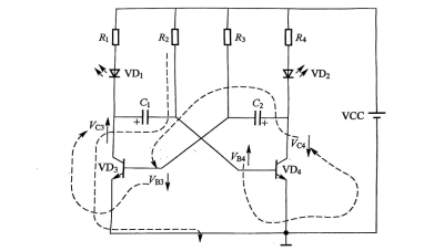
Figure 1.3. Circuit state after transistor VT4 is turned on.
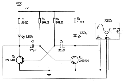
Figure 1.4 RC multivibrator circuit
The output waveform of the oscillating circuit is shown in Figure 1.5 (the resonant frequency is approximately 3.9 Hz).

Figure 1.5 Output waveform of the oscillating circuit
We will rearrange the layout of the circuit shown in Figure 1.4, as shown in Figure 1.6.
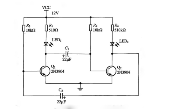
Figure 1.6 RC multivibrator circuit after layout modification
It is essentially just two inverters connected in series through two RC circuits. We can also use two inverters to build an oscillator, whose basic structure is shown in Figure 1.7. The circuit operation relies on the capacitor charging and discharging characteristics of the RC networks to generate the oscillation.

Figure 1.7 Multivibrator circuit constructed using inverter gates.
Working principle of RC multivibrator circuit explained in detail, showing how capacitor charging and discharging with positive feedback generates square wave oscillations for LED running lights and electronic circuit design. Click here for more information about capacitors https://xuansncapacitor.com