🔊In the production of aluminum electrolytic capacitors, increasing the capacitance value per unit volume is the direction of continuous improvement of capacitors. The capacitance is proportional to the effective area of the electrode surface, so the most effective way to expand the capacitance of aluminum electrolytic capacitors is to increase the effective surface area of the aluminum foil❗️The principle of corrosion technology of aluminum foil of electrolytic capacitor is like this
How to expand the effective surface area of aluminum foil of electrolytic capacitor❓
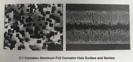
Currently, electrochemical corrosion is used for production. After corrosion, a large number of corrosion holes will be formed on the surface of the aluminum foil, as shown in Figure 3-1, which greatly increases the surface area of the electrode.
This article will introduce the corrosion technology of aluminum foil for electrolytic capacitors.
⌛️ 1.1 Influence of parameters of corroded aluminum foil on electrolytic capacitors
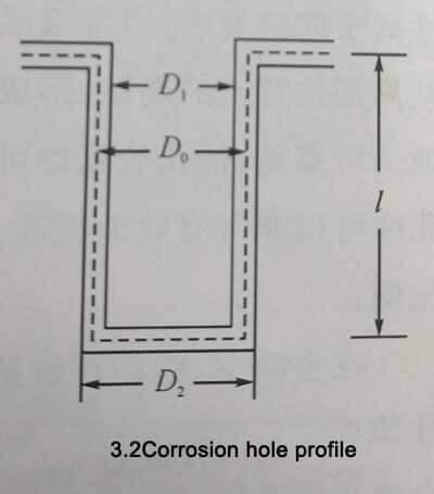
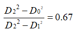
D0 represents the diameter of the etched hole when the oxide film is not formed, and D1 and D2 represent the inner diameter and the outer diameter of the etched hole after the oxide film is formed, respectively. L is the depth of the etched hole, and the thickness of the oxide film is d. L»D0 is generally used in actual production. Therefore, the bottom area of the etched hole is negligible. Take the density of aluminum as 2.7g/cm3 and the density of the oxide film as 3.4g/cm3. Assuming that the oxide film is formed in strict accordance with the stoichiometric ratio of A12O3, there are
Formula 3-1

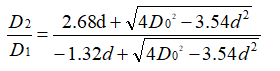
Therefore: Equation 3-2
At the same time, according to the geometric relationship, the thickness of the oxide film satisfies the formula 3-3
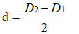
You can get: Equation 3-4
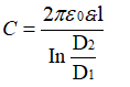
On the other hand, according to the cylindrical capacitance formula, the capacitance of a single cylindrical pit is: (Equation 3-5)
Assuming that the pit depth is the same, the pit spacing is p, and the distribution is hexagonal close-packed, the specific capacitance of the sample is: (Equation 3-6)
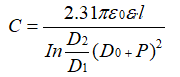
📌From formula (3-4) and formula (3-6), it can be seen that the deeper the etching hole depth L, the smaller the etching hole spacing P, the smaller the etching hole size D0, the smaller the oxide film thickness d, The smaller the etched foil. The larger the specific capacitance Cp value is. It should be pointed out that the pit depth L is limited by the thickness and strength of the aluminum foil of electrolytic capacitor and cannot be increased indefinitely. In addition, in addition to not being blocked and buried by oxides, the effective etching holes of the anode corrosion foils of practical electrolytic capacitors also need to leave gaps for the electrolyte to penetrate, forming sufficient electrical paths to effectively function as electrodes.
⌛️ 1.2 Corrosion mechanism of aluminum foil for electrolytic capacitors
Usually the result of electrolytic corrosion is polishing, roughening and pitting. Polishing does nothing to increase the surface area, while roughening only increases the surface area to a certain extent. On the other hand, in the solution containing some active ions on the metal surface covered by the passivation film, when the solution composition, polarization potential and temperature reach critical conditions, corrosion that is highly concentrated in some local positions on the surface will occur, forming corrosion holes, this corrosion is called pitting. The characteristic of pitting corrosion on passivated metal surfaces is that the corrosion can develop deep in the pits, while the passivation film remains on the metal surface outside the pits. Therefore, pitting corrosion can effectively increase the metal surface area.
Among metals, chromium and molybdenum are the most easily passivated, followed by nickel and iron, and valve metals such as aluminum, titanium and tantalum are more easily oxidized. The passivation properties of metals are not only determined by the properties of the metal itself, but also closely related to the properties of the solution in contact with it. Besides thiocyanate and bromide, the most typical reactive ion that causes pitting on passivated metal surfaces is chloride. Pitting corrosion occurs when aluminum is in a corrosive solution containing chloride ions.
📌1.2.1 Pitting corrosion of aluminum foil in high concentration hydrochloric acid solution
High voltage aluminum electrolytic capacitor anodic corrosion aluminum foil is usually prepared by anodic corrosion in about 2mol/L hydrochloric acid solution. In order to prevent the overall surface erosion of the aluminum material when it is corroded in high-concentration hydrochloric acid, some surface protective agents should be appropriately added. agent. Commonly used surface protectants include organic corrosion inhibitors, or inorganic acids and salts that can form purification films. Since organic corrosion inhibitors generally work by forming a continuous or discontinuous adsorption layer on the metal surface, this will inhibit the corrosion of the entire metal surface, which runs counter to the original intention of surface expansion corrosion. Therefore, inorganic acids and salts that form passive films are generally used as surface protective agents for surface swelling corrosion. These complex anions may have strong oxidizing properties, form a passivation film on the metal surface or combine with the metal ions of the anode reaction product, form a metal insoluble salt film on the metal surface, and form a passivation film or an insoluble salt film on the metal surface. The porous film on the metal surface is formed under the action of strong acid and high concentration of strong aggressive anion CI-, so the existence of these surface film layers can control the occurrence and development of pitting corrosion on the surface of aluminum foil. Taking the addition of H2SO4CrO3 or HF as an example, the electrolytic pitting corrosion process of aluminum in 2mol/L HCl was studied.
🔸(1) Research methods
Take the annealed aluminum foil samples and cut them into rectangular strips with a size of 20mmX100mm. Cover the shaded part in Figure 3-3 with polyurethane enamel, leaving an area of 10mmX10mm as the experimental area (the reverse side of the aluminum foil is also painted with enamel).
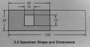 Figure 3-3
After the enamel base is dry, soak it in 1mol/L NaOH for 10min, then soak it in 4/%HNO3 for 30S, and wash it with deionized water. After that, using different electrolytic etching solutions and saturated calomel electrodes as reference electrodes, the cyclic voltammetry characteristics were tested in the range of -0.2~0V, the scanning speed was 0.2V/s, and the cycle was repeated 3 times. After three potential cycles, the samples were washed with pure water and then anodized in 10% ammonium adipate solution at 87 ± 2 °C and 20 V for 15 min using the constant current-constant pressure method. Then in 10% ammonium adipate solution, under the condition of 30±1℃, 120Hz, test its electrostatic capacity. Finally, the surface morphology of the samples was observed using a scanning electron microscope.
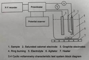 Figure 3-4
The electrolyte used for corrosion is shown in Table 3-1.
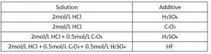 Table 3-1
🔸(2) Use 2 mol/L HCl solution alone
When aluminum is electrolytically corroded in HCl solution, the electrode reaction is: (Equation 3-7)
![]()
The cathodic reaction is (Equation 3-8)
![]()
Figure 3-5 is the cyclic voltammetry characteristic curve of aluminum under the conditions of 2mol/L HCl and 30℃. The potentials corresponding to points a, b, c, d, and e are the passivation film breakdown potential (Ebd), anode reversal potential or anode current peak potential (Eap), and repassivation potential (ErP), respectively. Hydrogen generation potential (EH) per cathodic reversal potential or cathodic current peak potential (Ecp). Between EH and Ebd is the passivation zone of aluminum.
As can be seen from Figure 3-5, compared with the saturated calomel electrode potential, the breakdown potential Ebd of the passivation film is -750mV, the anodic current peak potential Eap is -100mV, the repassivation potential Erp is -925mV, and the hydrogen production The potential EH was -1.5V, and the cathodic current peak potential was -2V. As the number of cycles increases, the peak current density of the anode gradually increases, indicating that during the measurement of cyclic voltammetry characteristics, the aluminum sample is strongly corroded on the one hand, and the effective surface area of the sample is increasing on the other hand. on the other hand. on the other hand. Pitting phenomenon.
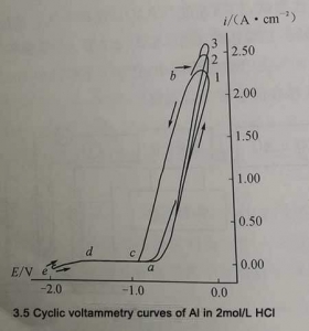 Figure 3-5
After three cycles, the specific capacitance of the sample was 0.5UF/C㎡, while the specific capacitance of the sample without cycling test was 0.25UF/C㎡. After the cycle experiment, a certain degree of pitting corrosion appeared on the surface of the aluminum foil, which doubled its surface area.
From the surface morphology of the samples after the cycle test given in Figure 3-6(a), it can be seen that the size and density of the etched holes are uniform. After enlarging part of the photo (as shown in Figure 3-6(b)), it can be seen that the shape of the etching hole is that each etching hole is composed of many small square holes, and the corrosion shows obvious anisotropy. The side length of the etched hole is about 20um. This phenomenon shows that when 2mol/L HCl solution is used alone as the etching medium, the walls of the etched holes are not effectively protected, and the lateral size of the etched holes increases too quickly, resulting in the merging of the etched holes. If the pit density is too low, degumming will occur. This trend is not conducive to increasing the pit density,
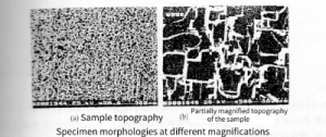 Figure 3-6
🔸(3) Add H2SO4 to 2mol/L HCL
After adding H2SO4 solution to 2mol HCL, the reaction occurs during the prevention:
![]()
The shape of the cyclic voltammetry curve is roughly the same as that of the 2mol/L HCL solution alone. The difference is that the breakdown potential Ebd of the passivation film moves to the positive direction, and the peak current of anodic polarization becomes smaller. Since the repassivation potential Ebd remains unchanged, the anodic polarization curve broadens in the potential direction and compresses in the current direction, as shown in Figure 3-7.
 Figure 3-7
Figure 3-8 shows the relationship between the breakdown potential Ebd of the passivation film and the amount of H2SO4 added. With the addition of H2SO4, the breakdown potential Ebd of the passivation film moves to the positive potential direction, because the addition of H2SO4 makes the surface of the aluminum foil passivated, and the structure density and thickness of the film increase。
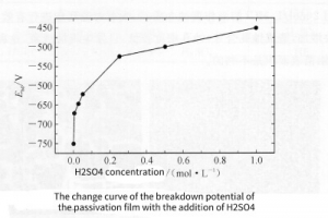 Figure 3-8
With the increase of H2SO4 addition, the concentration of H2SO4 increased. Due to the enhanced passivation ability of the solution, the pitting energy gradually decreases. The surface morphology of the samples after cyclic voltammetry is shown in Figure 3-9. The pore density gradually decreases with the increase of H2SO4 concentration, so the specific capacitance of the sample decreases gradually, as shown in Figure 3-10. But after adding H2SO4, compared with using HCl alone, the surface peeling of aluminum foil is effectively suppressed.
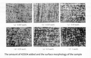 Figure 3-9
🔸 (4) Add CrO3 to 2mol/L HCl
When CrO3 is added to the hydrochloric acid solution, a hydrolysis reaction occurs first to generate CrO42-
![]()
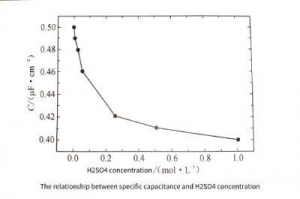 Figure 3-10
Then CrO42-: acidification occurs to generate Cr2O72-
![]()
Since Cr2O72- has strong oxidizing properties under acidic conditions, the passivation of the solution must be increased when CrO3 is added. In addition, since the reduction reaction of Cr2O72- can take place at the cathode, generating:
![]()
Therefore, a strong current peak appears in the cathode part of the cyclic voltammetry curve. A current inflection point appears on the cathode curve due to the hydrogen evolution reaction at the cathode. The cyclic voltammetry characteristics of the curve shape are shown in Figure 3-11. Similar and Erp unchanged. The cathodic polarization part is completely different. Not only is the current density greatly increased during cathodic polarization, but also the shape of the characteristic curve is different in the cathodic polarized part. ) becomes inconspicuous. This is mainly because the cathodically polarized hydrogen evolution reaction when H2SO4 is added is replaced by the reduction reaction when CrO3 is added (see equation (3-12)).
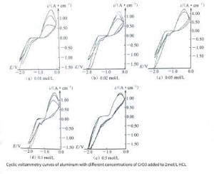 Figure 3-11
The transition from cathodic polarization to anodic polarization tends to be insignificant with the increase of CrO3 addition. When the addition amount of CrO3 is 0.5moI/L, the transition zone almost disappears. As shown in Figure 3-11(e). The shape and current of the anodic polarization curve did not change, indicating that the degree of anodic corrosion remained unchanged under each condition, which can also be seen from the surface morphology of the corroded samples shown in Figure 3-12. Since the anodic peak current when CrO3 is added is much smaller than the anodic polarization peak current when 2mol/L HCl is added alone, it can be seen that the corrosion degree is obviously weakened when CrO3 is added. Furthermore, similar to the case when sulfuric acid was added,
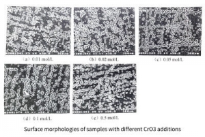 Figure 3-12
🔸 (5)Add 0.5mol/L CrO3 and H2SO4 to 2mol/L HCl
It can be seen from the above that the addition of H2SO4 enhances the passivation ability of the solution to aluminum and weakens the corrosion ability. The same is true when adding 0.5mol/L CrO3 and H2SO4 to 2mol/L HC. When the cyclic voltammetry curve shows anodization, the peak anode current decreases. In addition, due to the passive film covering part of the surface of the aluminum samples, the effective surface area during cathodic polarization decreases, resulting in a decrease in cathodic peak current during cathodic polarization. The transition from cathodic to anodic polarization disappears. During the scanning process from cathodic polarization to anodic polarization, the relationship between polarization current and polarization potential is almost a straight line, that is, the whole process is almost controlled by the ohmic resistance of the passivation film. A typical cyclic voltammetry characteristic curve is shown in Figure 3-13.
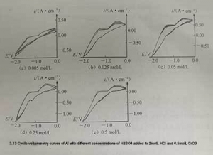 Figure 3-13
The peak anodic current during anodic polarization tends to increase with the number of cycles. This is due to the high density pitting corrosion on the surface of the aluminum foil samples. And the porosity keeps expanding and deepening, which is caused by the increase of the surface area of the sample. When adding 0.5moI/L Cro3 and H2 SO4 to 2moI/L HC at the same time, the passivation ability of the solution is greatly improved, the pitting corrosion is more difficult to occur, and the pitting corrosion density is smaller, but the strong protective ability greatly enhances the effect of surface erosion . The surface morphology of the sample after the cycle test is shown in Figure 3-14, and the change curve of the specific capacitance of the sample with the amount of H2SO4 added is shown in Figure 3-15.
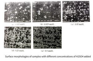 Figure 3-14
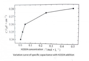 Figure 3-15
🔸 (6)Add 0.5mol/L CrO3, 0.5mol/L H2 SO4 and HF to 2mol/L HCl
Because HF has a strong dissolving effect on the passivation film, when HF is added to the dissolved 2mol/L HCl+0.5mol/L CrO3+0.5mol/L H2 SO4, the cyclic voltammetry curve of the aluminum sample changes greatly. . The addition of HF leads to the dissolution of the passive film, which promotes the corrosion of aluminum during the anodic polarization process, and also accelerates the reduction process of Cr2 0 during the cathodic polarization process. The polarization peak current increases at the same time, as shown in Figure 3-16.
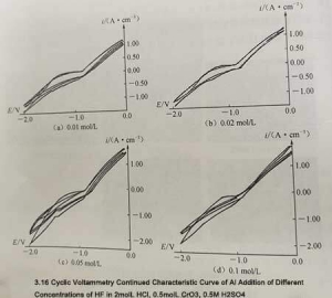 Figure 3-16
Figure 3-16 is quite different from the previous curve shape, the area enclosed by the loop curve becomes smaller during the scan. This is because the presence of HF greatly promotes the dissolution process of the passivation film and reduces the polarization overpotential caused by the additional polarization caused by the passivation film. Even with the addition of only 0.01 moI/L HF, the shape of the cyclic voltammetry curve is quite different from that without the addition of HF, and the anodic polarization current density and cathodic polarization current density increase significantly. When HF was further added, the current density was 2. Polarization increases significantly. Density growth slowed.
Figure 3-17 shows the surface topography of samples with different concentrations of HF added. It can be seen that the surface pit density of the samples increases uniformly with the increase of the added HF concentration, which is consistent with the trend that the anodization peak current increases with the increase of the HF concentration. Samples after cycle testing. The trend of increasing specific capacitance with increasing HF concentration is consistent (see Figure 3-18)
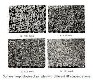 Figure 3-17
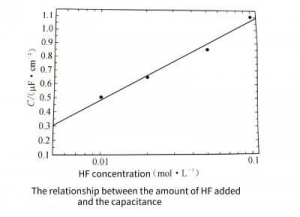 Figure 3-18
🔸 (7) Summarize
By adding different kinds and different concentrations of additives to aluminum foil samples in 2moI/L HCl and 2moI/L HCl solutions, the following conclusions were drawn: In 2moI/L HCl solution, the aluminum foil samples not only had strong pitting corrosion, but also Erosion will occur. After the addition of H2SO4 and CrO3, the passivation ability of the solution is enhanced, and the protection ability to the surface corrosion of the sample is enhanced, but the pitting corrosion ability is decreased. On this basis, adding a small amount of HF can not only have a strong dissolving effect on the passivation film, but also uniformly generate high-density pitting corrosion and effectively prevent surface corrosion.
📌 1.2.2 Pitting starts and growing textures
The research in the previous section shows that the electrolytic corrosion of aluminum in the mixed solution of 2moI/L HCl+0.5moI/L Cro3+0.5moI/L H2 SO4 +HF has good pitting corrosion characteristics, and the surface formation density of the sample is high and the distribution is uniform. No corrosion on the surface. The following analysis of this phenomenon
🔸 (1) Metal Surface Conversion Coating
When a metal is in a certain medium, the transition from the active metal to the corresponding passivating compound always occurs spontaneously due to thermodynamic instability. If this transformation results in the formation of a stable compound that has strong adhesion and is insoluble in water or a given medium, the compound formed on the metal surface is called a chemical conversion coating. Biestek (T.Biestek) and Weber (J.Weber) proposed to use the following reaction formula to strictly define and express the formation of chemical conversion membrane:
![]()
The media that can form a chemical conversion film on the metal surface include sulfuric acid and sulfate, phosphoric acid and phosphate, chromic acid and dichromate, etc.
🔸 (2) Surface Conversion Coating During Corrosion of Aluminum Foil
When aluminum is anodic corrosion in 2moI/L HCl+0.5moI/L Na2 Cr2O7 +0.5moI/L H2SO4 +0.1 moI/L HF electrolyte, the cathodic reaction is
![]() Formula 3-14
Formula 3-14
![]() Formula 3-15, same as 3-12
Formula 3-15, same as 3-12
The reduction reaction of Cr2O72- can take place at the cathode (on the graphite electrode) or on the surface of the aluminum foil. Cr2O72- is attracted to the surface of the aluminum foil under the action of the electric field, and directly reacts with Al on the surface of the aluminum foil to form Cr3+. Because of the reaction expressed by the equation. (3-16) A large amount of H+ is consumed on the local surface of the anode, and the nearby pH value increases, causing the following additional reactions at the anode:
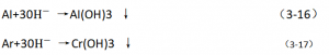 Formulas 3-16 and 3-17
Meanwhile, the anodic reaction is:
![]() Formula 3-18
Formula 3-18
Since there is a layer of natural oxide film on the surface of the aluminum foil sample, a layer of Al(OH)3 and Cr(OH) will be formed on the surface of the sample due to the progress of the reactions represented by formula (3-16) and formula (3-17). . form. 3 and the conversion film of complex composition composed of chromate and water, so that the reaction represented by formula (3-18) cannot occur directly on the surface of aluminum foil. If the solution contains a certain amount of fluoride ions, the fluoride ions will corrode the natural oxide film and the conversion film, and expose the surface of pure aluminum, so that the subsequent reaction can proceed smoothly. The chloride ions and sulfate ions in the solution also have a certain dissolving effect on the natural oxide film.
Due to the corrosion of active anions, the conversion film on the surface of the aluminum foil will form a double-layer structure film with the porous layer as the outer layer and the dense layer as the inner layer, as shown in Figure 3-19. (1).
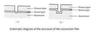 Figure 3-19
The conversion film can prevent the further dissolution of aluminum, but when the content of active anions reaches a certain content, the dense layer at the bottom of the pores of the conversion film will be attacked and dissolved by the active anions, and the underlying aluminum can be corroded. At the same time, since the current is concentrated at the pit position, the reactions represented by equations (3-16) and (3-17) can occur here, thereby forming the conversion film again. The newly formed conversion coating can crack again, dissolve, and then form a conversion coating. During the alternating process of dissolution→formation→redissolving→reformation of the conversion film at the bottom of the hole, the etched hole gradually deepens, as shown in Figure 3-19(b). At this time, the thickness of the conversion film,
🔸 (3) Conversion coating controls the corrosion process of aluminum foil
In the first few seconds of electrochemical corrosion, there is a natural oxide film on the surface of the aluminum sample, and the corrosion resistance of the natural oxide film is different at each position. The native oxide film in dislocation, defect, or impurity-rich regions is preferentially dissolved by active anions, resulting in preferential formation of conversion films in these regions. Once the conversion film is formed, its pore bottoms are destroyed by reactive anions to initiate initial pitting corrosion. After the initial etching starts, since there is no transfer film at the bottom of the transfer film hole, the current is concentrated, so that the transfer film is re-formed at the bottom of the hole, which may be broken again, and then the transfer film is formed again. When the potential at the bottom of the hole is too late to diffuse the dissolved aluminum ions into the solution or the ohmic potential in the etching hole drops to the repassivation potential, the growth of the etching hole stops. The process that the dense layer at the bottom of the conversion film is attacked and dissolved by active anions is the initiation process of the pit, and the process of dissolution→formation→redissolving→reforming of the conversion film in the hole is the initiation process of the pit. pit growth process. In a mixed solution containing HCl, H2SO4, H2Cr2O7, and HF, the initiation and growth of pores in the aluminum samples were controlled by the structure of the conversion coating. The growth of the etched hole stops. The process that the dense layer at the bottom of the conversion film is attacked and dissolved by active anions is the initiation process of the pit, and the process of dissolution→formation→redissolving→reforming of the conversion film in the hole is the growth process of the pit. In a mixed solution containing HCl, H2SO4, H2Cr2O7, and HF, the initiation and growth of pores in the aluminum samples were controlled by the structure of the conversion coating. The growth of the etched hole stops. The process that the dense layer at the bottom of the conversion film is attacked and dissolved by active anions is the initiation process of the pit, and the process of dissolution→formation→redissolving→reforming of the conversion film in the hole is the initiation process of the pit. pit growth process. In a mixed solution containing HCl, H2SO4, H2Cr2O7, and HF, the initiation and growth of pores in the aluminum samples were controlled by the structure of the conversion coating.
At the same time, with the prolongation of the corrosion time, the natural oxide film on the surface of the sample is all dissolved by active anions, resulting in the formation of a conversion film on the entire surface of the sample, so that the surface of the entire surface of the sample is etched and develops continuously along the depth direction. . Since the porosity and pore size of the conversion film are determined by the corrosion conditions, the distribution of corrosion pores can be successfully controlled only by adaptively controlling the composition, temperature and current density of the electrolyte. Furthermore, surface erosion phenomena during the initiation and growth of the etched holes are avoided because the regions between the etched holes are protected by the conversion coating.
🔸 (4) Initial position of pitting
To explore the relationship between pit location and impurities, samples were prepared by galvanostatic corrosion test, and the surface morphology and elemental composition of the corroded samples were analyzed by scanning electron microscope (SEM) equipped with energy dispersive X-. Radiographic Analysis (EDS) Equipment. Figure 3-20 shows the surface morphology of the samples after H2SO4 pretreatment before the galvanostatic corrosion test. The H2SO4 immersion pretreatment not only removes the oil and dust on the surface, but also has a certain activation effect on the surface.
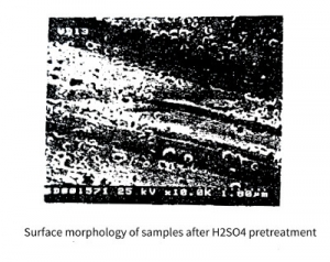 Figure 3-20
The principle of galvanostatic corrosion test is shown in Figure 3-21. The experimental area is 40 mm × 100 mm on both sides, and the electrolyte is a mixture of 2moI/L HCl+0.5moI/L Na2Cr2O7+0.5mol/L H2SO4+0.1mo/L HF. To keep the electrolyte conditions relatively consistent when testing different samples, 0.1 mol/L of aluminum was dissolved in the mixed electrolyte. The electrolyte temperature was kept at 80±1°C, and the applied DC current density was 250mA/. Since both sides of the sample were corroded at the same time, the actual applied current density on each side was 125 mA/. The constant current test time is 0, 5, 10, 15, 20, 30, 40, 50, 60 seconds. After testing, samples were rinsed with deionized water and then dried for speciation and elemental analysis.
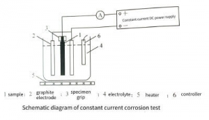 Figure 3-21
Figure 3-22 shows the surface morphologies of the samples when the galvanostatic corrosion time is 5, 10, 15, 20, 30, 40, 50 and 60S, respectively. White areas are corroded areas and black areas are uncorroded areas. It can be seen that with the prolongation of corrosion time, the corroded area continues to expand, and the uncorroded area continues to shrink. When the etching time exceeds 30S, the corrosion area expands to the whole surface, but when the etching time is shorter (less than 30S), the corrosion pores are clustered instead of uniformly distributed, which indicates that the initial starting position of corrosion is incomplete. It is more likely to randomly appear in impurity element-rich regions, grain boundary regions, dislocation regions or defect regions.
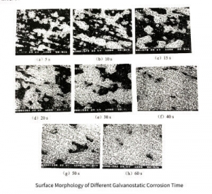 Figure 3-22
From Figure 3-22 (a) and (b), it can be seen that the corrosion areas are clustered on the raceway line, indicating that the raceway location is the location where the corrosion pits are initially generated. From the perspective of the aluminum foil rolling process, the rolling marks are formed due to the strong fragmentation of the grains or the fragmentation of the enriched impurities, so the position of the rolling marks is the dislocation or defect enrichment area or the impurity enrichment area. The fault or defect region contains larger lattice distortion energy and therefore has a higher chemical formula. On the other hand, for the impurity region, since aluminum is an active metal and impurities such as iron and copper are inert metals, when impurities such as iron and copper are enriched in aluminum, these impurities become local cathodes in aluminum, resulting in the trapping of impurities surrounded. Aluminum corrodes preferentially.
To further explore the reasons for preferential corrosion, elemental analysis was performed on the corroded and uncorroded regions. The EDS spectrum is shown in Figure 3-23, and the element composition is shown in Table 3-2.
![]() Table 3-2
Table 3-2
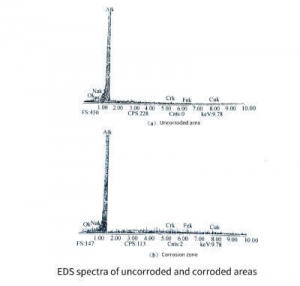 Figure 3-23
It can be seen from Table 3-2 that most of the surface of the sample is aluminum in both the corroded area and the uncorroded area. The elemental composition of the unetched regions is relatively simple. Apart from AI, there are only O and Na signals. Na can be considered to be caused by the solution remaining on the surface of the sample, while O is caused by the presence of an oxide film on the surface of the unetched area. Besides O and Na, there are some Fe and Cu signals in the corroded region. Since these two elements do not exist in the solution, these Fe and Cu can only be the original impurities inside the aluminum foil. Therefore, elemental analysis indicates that the initiation of the initial etch pits is more likely to occur in impurity-rich regions.
🔸 (5) Kinetic Parameters of Aluminum Corrosion in Mixed Acid Solutions
When the electrode is in a polarized state, the polarization current density is:
![]()
In the formula: E is the electrode potential when the electrode polarization current density is i, that is, the polarization potential, Ecorr is the natural potential or corrosion potential of the electrode: i corr is the current density at the corrosion potential: △E = E-Ecorr: βa and βc are the natural logarithms of the Tafel constants for the anodic and cathodic reactions, respectively. When ΔE>0, it is anodic polarization, otherwise it is cathodic polarization.
The above content is an introduction to the technical principle of electrolytic capacitor aluminum foil corrosion. In the next article, we will introduce the technical principle of electrolytic capacitor aluminum foil energization.