1.Width Expansion of Capacitor Material Metals
Width spread refers to the change in the width of a rolled piece during the rolling process, also known as transverse spread. It affects the non-uniformity of deformation in the width direction. There are two methods to represent width spread: absolute width spread and relative width spread. Absolute width spread is the difference in width of the rolled piece before and after rolling, i.e., ∆b = b1 – b0; relative width spread is the ratio of the difference in width of the rolled piece before and after rolling to the width before rolling, i.e., ∆b/b0. This article uses the capacitor material metal produced by XUANSN as an example for explanation.
1.1 Components of Width Expansion
Width expansion is a complex deformation process, comprising the following three components:
1.1.1 Slip Width Expansion. When a rolled piece is compressed upwards, if there is no friction at the contact surfaces at both ends, the metal will slide in various directions; transverse sliding constitutes slip width expansion.
1.1.2 Lateral Transfer Width Expansion If the frictional force on the contact surfaces is high, sliding cannot occur between the two contact surfaces, forcing the metal on the side to transfer and become a new contact surface, resulting in lateral transfer widening.
1.1.3 Lateral Deformation Widening. Due to the frictional resistance at the contact surfaces, the metal near the contact surface lags behind the metal farther from the contact surface, resulting in lateral deformation widening.
The sum of these three factors constitutes the entire widening.
In Figure 1, ∆b1‘, ∆b1” and ∆b1”’ represent the slip width, lateral transfer width, and lateral deformation width, respectively. The total width A6 should be the sum of the above three, that is:
![]() (1)
(1)
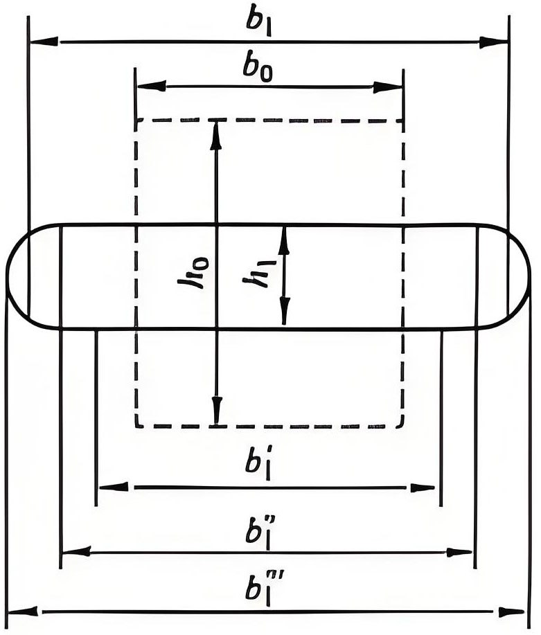
Figure 1 Composition diagram of width
1.2 Factors affecting width
Various conditions during rolling affect width. The main influencing factors include reduction, height and width of the rolled piece, roll diameter, chemical composition of the rolled piece and rolls, surface condition of the rolls, rolling temperature, and lubrication conditions during rolling, as shown in Figure 2. As shown in Figure 2, these influencing factors are particularly crucial for controlling the final width spread when processing materials with high dimensional stability requirements, such as capacitor material metals. XUANSN strictly controls these factors during the production process.
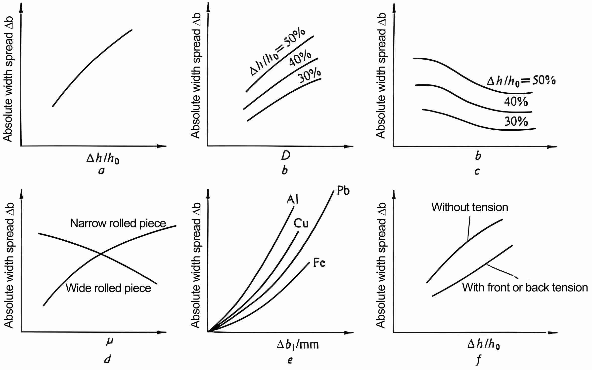
Figure 2: Influence of various factors on width spread
a- Influence of processing rate; b- Influence of roll diameter D; c- Influence of workpiece width b; d- Influence of friction coefficient μ; e- Influence of workpiece chemical composition; f- Influence of tension
As shown in the figure, when the workpiece height decreases, the width and length inevitably increase. Therefore, the greater the processing rate during rolling, the greater the width spread of the workpiece. When other conditions are the same, an increase in roll diameter, an increase in bite arc length, and an increase in resistance along the extension direction of the metal result in a corresponding increase in width spread.
The influence of the friction coefficient varies with the shape of the deformation zone. Figure 3 shows two shapes of the deformation zone during rolling. The deformation zone for profile rolling and narrow strip rolling is narrow and long, as shown in Figure 3a; the deformation zone for plate rolling is wide and short, as shown in Figure 3a. As shown in b. When the coefficient of friction increases, the Py force in the narrow and long deformation zone increases, forcing the metal to expand more to both sides, i.e., the width increases; for the wide and short deformation zone, the Pz force increases, and therefore the width expands less. So when rolling wide plates, the width expands very little and can be ignored.
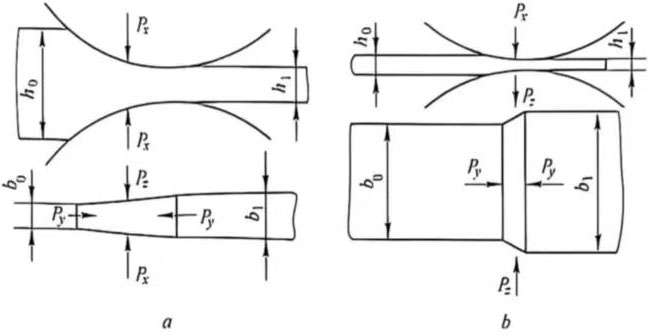
Figure 3 Rolling Deformation Zone
a-Section and Narrow Strip Rolling; b-Plate Rolling
The chemical composition of the metal and rolls, rolling temperature, and lubrication conditions affect the width spread through their influence on the coefficient of friction, and are determined by the shape of the deformation zone. In actual rolling of high-precision such capacitor material metals, the effects of these factors are even more pronounced.
The front and back tension during rolling is a factor that reduces the width expands. In some cases, the use of tension may result in a negative width expand, which reduces the width of the rolled piece.
1.3 Calculation of Width Expands
There are many formulas for calculating width expands. Here, we only introduce a semi-empirical formula that is widely used in flat roll rolling of non-ferrous metals:
![]() (2)
(2)
where C — constant; for aluminum, C = 0.45 at around 400℃.
This formula considers key factors such as the influence of deformation zone length and processing rate on width spread, but does not consider the influence of workpiece width. Therefore, this formula is not applicable to rolling conditions where the workpiece width is equal to or less than its thickness.
1.4 Practical Significance of Width Spread
During flat roll rolling, due to the influence of width and uneven deformation, secondary tensile stress is generated at the edge of the workpiece, and secondary compressive stress is generated in the middle of the workpiece (see Figure 4). The generation of secondary tensile stress is the root cause of edge cracking, increasing geometric scrap loss. The greater the width spread, the greater the scrap loss. To reduce the losses caused by width spread, the following measures can be taken:
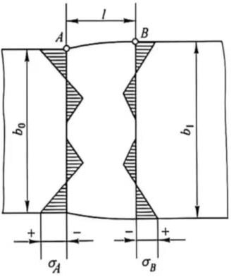
Figure 4 Secondary stress generated during flat roll rolling
(1) Reduce the coefficient of friction;
(2) Reduce the billet thickness;
(3) Appropriately distribute the reduction and rolling passes. These measures have been applied in XUANSN’s production practice.
2 Calculation of Rolling Force
2.1 Yield Strength
The yield strength of aluminum and aluminum alloys at which plastic deformation reaches 0.2% is called σ0.2. σ0.2 is an important parameter for calculating the rolling force of aluminum and aluminum alloys, and is particularly crucial in the processing of capacitor material metals where precise control of deformation characteristics is required. Yield strength is related to deformation temperature, deformation rate, and degree of deformation, as shown in Figures 5 and 6. For cold rolling, the main influencing factor is the degree of deformation.
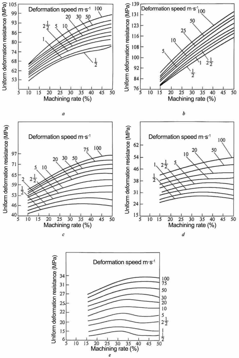
Figure 5: Influence of Deformation Temperature, Deformation Rate, and Degree of Deformation on the Yield Strength of Pure Aluminum a-150℃; b-250℃; c-350℃; d-450℃; e-550℃
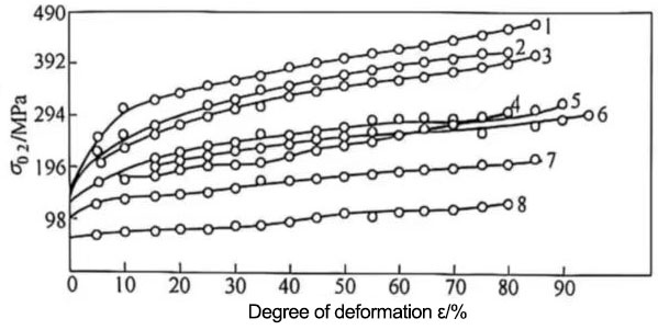
Figure 6 Relationship between yield strength and degree of deformation (t=20℃)
1-5A06;2-5A05;3-6A02;4-2A12;5-2A11;6-2A02;7-3A21;8-1035
In uniaxial rolling, the yield strength of the material is the deformation resistance, also known as the forced flow stress of the metal. In the rolling of sheet and strip, since the metal particles are in a triaxial compressive stress state, its forced flow stress is different from the yield limit in uniaxial tension, denoted by K:
![]() (3)
(3)
2.2 Rolling force
Rolling force is a crucial parameter in the design and control of rolling processes and equipment. It serves as an important basis for calculating the strength and elastic deformation of rolls and other mill components, verifying or determining motor power, establishing reduction regimes, achieving automatic control of plate thickness and shape, maximizing equipment potential, and improving labor productivity. Accurate calculation of rolling force is particularly critical when processing materials with high requirements for thickness accuracy and plate shape, such as capacitor material metals.
Rolling force refers to the vertical component of the resultant force exerted by the workpiece on the rolls. As mentioned earlier, during rolling, the metal exerts two forces on the rolls: one is the unit frictional force T tangential to the contact surface; the other is the resultant force N of the unit pressure perpendicular to the contact surface. The rolling force is the sum of the projections of these two forces perpendicular to the rolling direction, PH (see Figure 7).
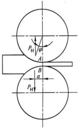
Figure 7. Stress analysis diagram under simple rolling conditions
The basic formula for calculating rolling force is:
![]() (4)
(4)
Where F = bl, ![]() , then:
, then:
![]() (5)
(5)
Calculation steps for rolling force:
2.2.1 Calculate the forced flow stress K of the metal:
1) Calculate the average deformation rate
![]() (6)
(6)
- Calculate the degree of deformation
![]() (7)
(7)
3) Based on the obtained ū and ε values, look up the corresponding material values in Figures 5 and 6. σ0.2.
4) Calculate the corresponding K value according to the formula K=1.15σ0.2.
2.2.2 Calculate the average unit rolling force P
When calculating the cold rolling force, three factors need to be considered: the degree of work hardening of the material caused by the previous rolling passes; the elastic flattening of the rolls during rolling; and the effect of tension during rolling. For thin materials such as capacitor material metals, these factors have a particularly significant impact on the rolling force and need to be considered in detail.
1) Work hardening caused by processing rate. Since the cold rolling temperature is below the recrystallization temperature of the material, the work hardening generated in each pass cannot be eliminated. Therefore, when calculating the K value, the deformation should include the sum of the deformation of the previous passes, that is:
![]() (8)
(8)
![]() (9)
(9)
According to ε0 and ε1, the corresponding yield strength σ(0.2)0 and σ(0.2) can be obtained from the figure. 1. Calculation:
![]() (10)
(10)
![]() (11)
(11)
![]() (12)
(12)
2) The effect of cold rolling elastic flattening on rolling force. During cold rolling, due to the work hardening of the material, the roll produces elastic flattening. The projected length of the contact arc between the elastic flattening roll and the strip is extended from L to L’. Therefore, L’ should be considered when calculating the rolling force. L’ can be obtained with the help of Figure 8.
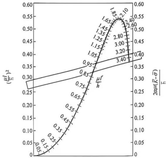
Figure 8 Calculation of the contact arc length after flattening using the graphical method
(For steel rolls, α=1.06×10⁻⁴R; for cast iron rolls, α=2.06×10⁻⁴R. If the straight line and the intermediate curve scale intersect at two points, the smaller value should be taken; if there is no intersection, it means that the processing rate used in this pass causes the roll flattening to be too large and cannot be rolled.)
Calculation steps of L’:
① Calculate![]() ;
;
② Calculate![]() ;
;
③ Obtain the value of ![]() from Figure 8, and calculate the value of L’ from
from Figure 8, and calculate the value of L’ from ![]() .
.
3) The effect of cold rolling tension on rolling force. During cold rolling, tension rolling is used, which reduces the average unit rolling force. Since both front and rear tensions affect the rolling force, the average value of front and rear tensions ![]() should be considered when calculating cold rolling tension. When rolling thin plates or foils with high requirements for thickness uniformity and plate shape, such as capacitor material metals, tension control is particularly important for stabilizing the rolling force.
should be considered when calculating cold rolling tension. When rolling thin plates or foils with high requirements for thickness uniformity and plate shape, such as capacitor material metals, tension control is particularly important for stabilizing the rolling force.
Generally, the magnitude of the front and rear tensions used can be determined according to the following empirical formulas depending on the thickness of the rolled piece:
![]() (13)
(13)
![]() (14)
(14)
After considering the three influencing factors for calculating cold rolling force, with the help of Figure 9 Find the pressure multiplier PMF value, and then calculate the average unit pressure P using the following formula:
![]() (15)
(15)
Finally, the cold rolling force is:
![]()
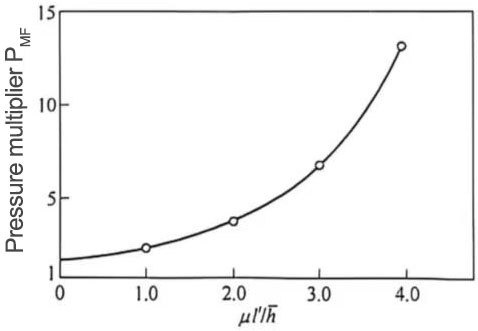
Figure 9: Relationship curve between pressure multiplier PMF and ![]()