1.Residual Stress in Capacitors Manufacturing
Residual stress refers to the secondary stress remaining in the deformed body after the external force is removed during the XUANSN capacitors manufacturing process. Residual stress can be caused by deformation, uneven heating and cooling, and uneven microstructure transformation. Residual stress, corresponding to secondary stress, is also classified into first-type, second-type, and third-type residual stress.
The presence of residual stress in an object can have serious effects. For example, it can make the deformation of the object more uneven, shorten the service life of the parts after processing, cause the size and shape of the object to change over time, and reduce the corrosion resistance and mechanical properties of the metal.
Methods to reduce and eliminate residual stress: During the manufacturing process of XUANSN capacitors, different heat treatment systems are used according to the different types of residual stress in the object; for objects with residual stress on the surface, mechanical methods can be used to add some surface deformation to generate new secondary stresses and residual stresses to offset or reduce the original residual stresses, such as surface rolling and surface stretching.
2.Bite Arc and Bite Angle
2.1 Relationship between Bite Arc, Bite Angle, and Reduction
The arc in which the workpiece and the roll come into contact is called the bite arc, as shown by arc AB in Figure 1. The central angle corresponding to arc AB is called the bite angle. The geometric relationship between the bite angle, roll diameter, and reduction is shown in Figure 2.
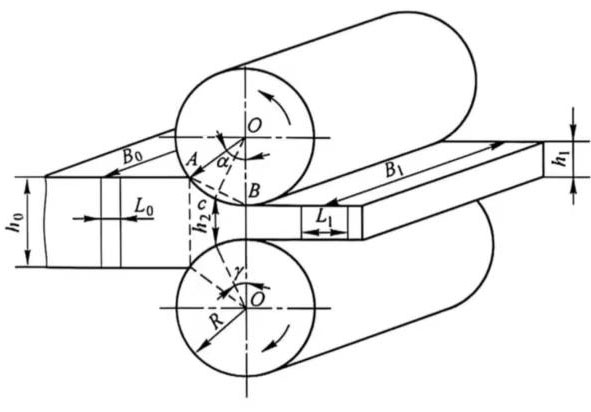
Figure 1 Schematic diagram of the deformation flow of rolled metal in three directions
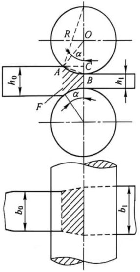
Figure 2 Deformation zone and bite angle during rolling
From Figure 2, we can see that:
![]()
![]()
![]()
![]()
![]() (1)
(1)
![]() (2)
(2)
Where a-bite angle.
2.2 Deformation Zone and Deformation Zone Length
The space enclosed by the bite arc, the side of the workpiece, and the entrance and exit surfaces of the workpiece is called the deformation zone.
The horizontal projection of the chord of the bite arc is called the deformation zone length L, as shown in Figure 2, AC = L.
In capacitors manufacturing, the control of this deformation zone has a significant impact on the material thickness accuracy and surface quality.
Calculation of Deformation Zone Length:
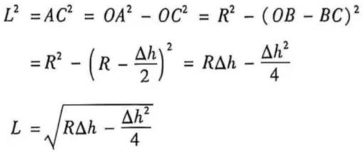 (3)
(3)
![]() (4)
(4)
2.3 Biting Conditions of the Rolled Workpiece
To achieve the rolling process, the rolled workpiece must first bite into the rolls, then fill the gap between the rolls, and then the rolling production can proceed. Practice has shown that to establish a rolling process, the biting conditions of the rolled workpiece must be met.
2.3.1 Biting Conditions at the Moment of Biting In
As shown in Figure 3, at the moment the workpiece bites in, each roll exerts two forces on the workpiece. One is a normal force (radial force) N perpendicular to the contact between the roll and the metal, and the other is a frictional force T at the point where the roll and the workpiece surface are tangential. The vertical components of N and T are in the same direction, causing compressive deformation of the metal; the horizontal components of N and T are in opposite directions. The horizontal component Tx attempts to pull the workpiece between the rolls, while the horizontal component Nx attempts to push the workpiece out of the rolls. From this, it can be seen that:
If Nx > Tx, the workpiece cannot be bitten in, and the rolling process cannot be established.
If Nx = Tx, the workpiece is in equilibrium, but it still cannot be naturally bitten in.
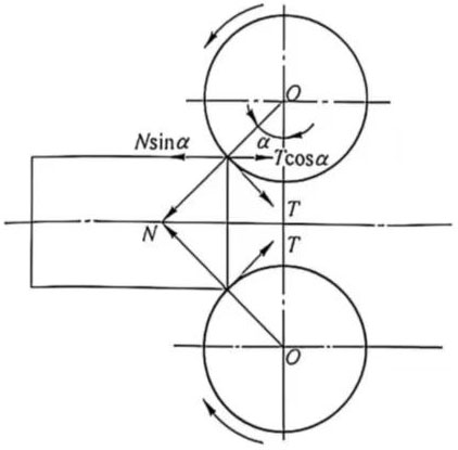
Figure 3 Forces at the instant of workpiece biting in
If Nx < Tx, the rolls can bite the workpiece in.
Therefore, if we disregard the inertial force during biting, the following conditions must be met to achieve biting:
![]()
While Tx = Tcosα = Nμcosα, Nx = Nsinα, then
![]()
![]() (5)
(5)
Let μ ≥ lanβ, then:
![]() (6)
(6)
Where μ is the coefficient of friction between the workpiece and the contact surface of the roll;
β is the friction angle.
Therefore, at the initial instant of the rolling process, the condition for the roll to bite into the workpiece is:
![]()
That is to say, the workpiece can only be bitten when the coefficient of friction is greater than the tangent of the biting angle, or when the friction angle is greater than the biting angle. The biting angle equal to the friction angle is called the limiting biting angle, or the maximum permissible biting angle. It can be seen that friction is beneficial to achieving the rolling process.
Table 1 lists the maximum bite angles commonly encountered in capacitors manufacturing under different rolling conditions.
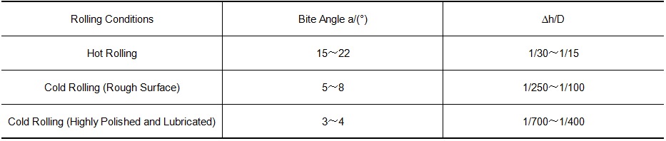
Table 1 Maximum Bite Angles under Different Rolling Conditions
2.3.2 Bite Conditions during Stable Rolling
As the workpiece is gradually bitten into and fills the space between the rolls, the contact area between the workpiece and the rolls gradually increases, and the point of application of the combined pressure of the rolls on the workpiece gradually moves inward. The relationship between the maximum bite angle and the friction angle changes accordingly. Let δ represent the angle corresponding to the arc of the portion not yet bitten in (see Figure 4).
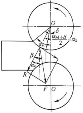
Figure 4 Bite Angle during the Workpiece Filling Process
Assuming the force on the arc of contact between the workpiece and the rolls is uniformly distributed, the point of application of the combined pressure can be assumed to be located at the midpoint of this bite arc. Let αz represent the angle between the radial line of the point of application of the combined pressure and the center line of the roll, and αM be the maximum bite angle at the start of biting. As the workpiece gradually fills the space between the rolls, δ gradually decreases, and αz also gradually decreases. From Figure 4, we can see the following relationship between αz, αM and δ:
![]()
Let the ratio of αM to αZ be n, that is:
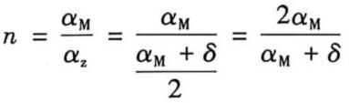 (7)
(7)
From the above formula, we know that at the moment of initial bite, δ=α, αM=αZ, that is, n=1; when the rolled piece is completely bitten in, δ=0, αM=2αZ, then n=2. The value of n varies between 1 and 2. According to the condition that the bite angle is less than the friction angle, that is:
![]()
The bite condition in the steady process can be obtained as:
![]() (8)
(8)
The maximum bite angle in the steady rolling process can increase compared to the moment of initial rolling, but because the force of the roll on the bite arc is not actually uniformly distributed, the rule of n=2 is not completely correct. Experimental results show that when cold rolling aluminum, the ratio n is close to 2.
- Forward Slip
In the rolling process of capacitors manufacturing, the speed at which metal is ejected from the roll is greater than the linear velocity of the roll circumference. This phenomenon is called forward slip.
It affects the uniformity of deformation of the rolled piece along the cross-section (thickness direction). The forward slip value can be expressed by the following formula:
![]() (9)
(9)
Where S-forward slip value;
V2-speed of the rolled piece leaving the roll;
V-circumferential linear velocity of the roll.
The forward slip value of cold rolling varies depending on the processing rate, tension, friction coefficient, etc., and is generally 0~6% under normal conditions.
3.1 Determination of Forward Slip Value
Experimental method: Make indentations on the surface of the roll at a distance of L0 (see Figure 5). After rolling, the indentation distance on the surface of the rolled piece is L1. The forward slip value can be calculated according to formula 5-17. This method is simple and accurate. Its disadvantage is that it can only measure surface slip and cannot measure internal slip of the metal.
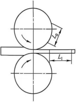
Figure 5 Determination of forward slip using the indentation method.
Calculation method:
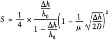 (10)
(10)
Where μ is the coefficient of friction between the roll and the workpiece;
D is the roll diameter;
∆h is the absolute reduction,∆h = h0-h1;
h0 is the thickness of the workpiece before rolling;
h1 is the thickness of the workpiece after rolling.
3.2 Main factors affecting forward slip
In the metal strip rolling process of XUANSN capacitors manufacturing, many factors affect forward slip, mainly including reduction, roll diameter, coefficient of friction, front tension, back tension, rolling speed, and workpiece width. Rolling temperature and alloy type are affected by the coefficient of friction. The influence of various factors on forward slip is shown in Figure 6.
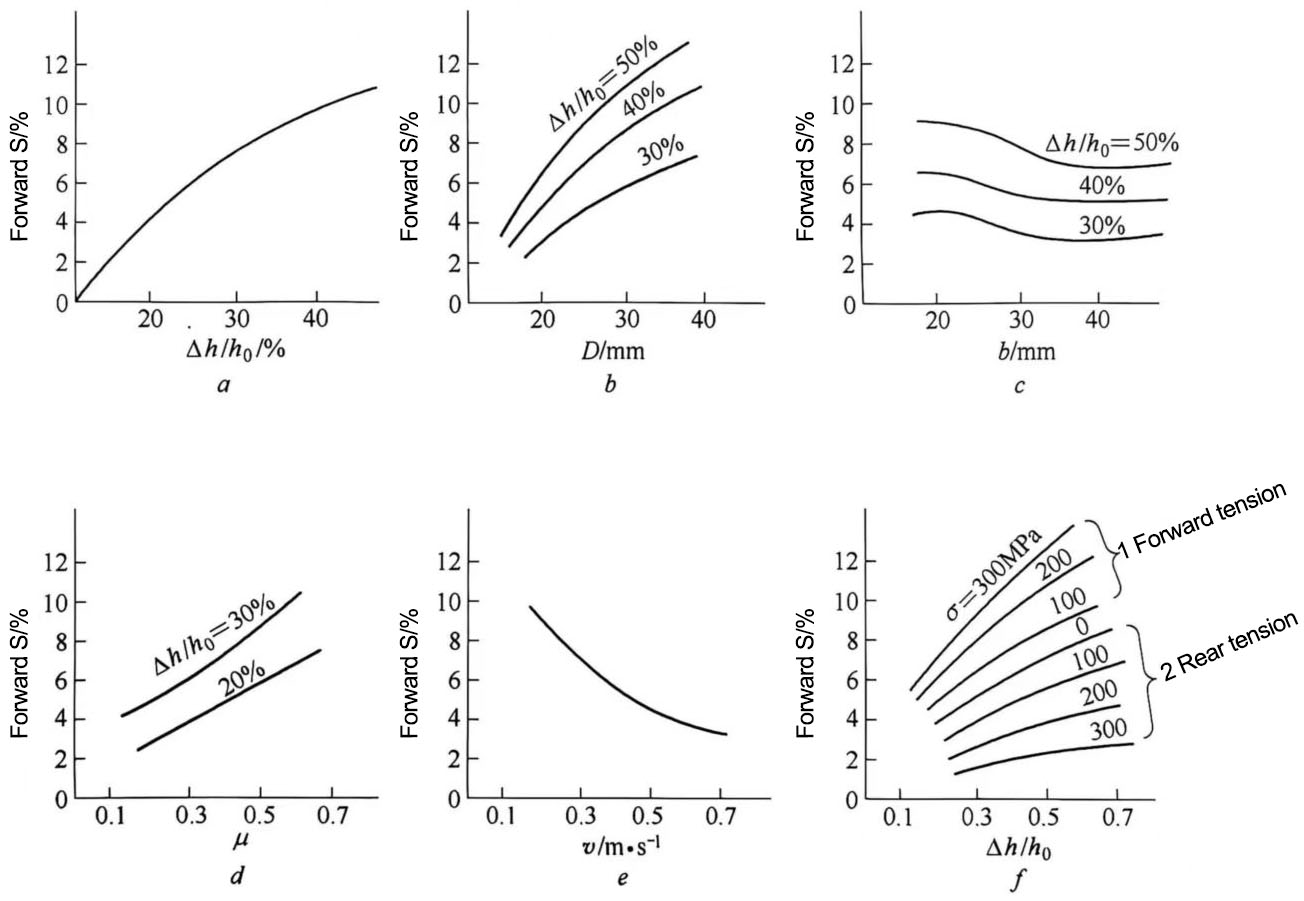
Figure 6 Influence of various factors on forward slip
a-Influence of processing rate; b-Influence of roll diameter D; c-Influence of workpiece width b; d-Influence of friction coefficient μ; e-Influence of rolling speed v; f-Influence of front and rear tension
3.3 Significance of forward slip in actual production
In cold rolling production, the value of forward slip is small, but it has important significance in the XUANSN capacitors manufacturing:
(1) The friction coefficient is a very important parameter in the rolling process. The friction coefficient is different at different points along the bite arc. The change in the friction coefficient directly affects the magnitude and distribution of the unit pressure in the deformation zone, thus affecting the consumption of rolling power. It is quite difficult to directly measure the friction coefficient from experiments, but it is easier to calculate the friction coefficient by measuring the forward slip value.
(2) When rolling under tension, especially under the conditions of using polishing rolls and good lubrication, it is possible to make the neutral point close to or even coincide with the exit point of rolling, that is, the forward slip value is greatly reduced, close to 0, or even negative. This can prevent the rolling mill from biting into the workpiece, causing the rolls to slip on the workpiece, and even causing the mill to vibrate, affecting product quality. To solve this problem, the front tension should be appropriately increased and the reduction adjusted to maintain a certain front slip value.
During the rolling process, the front slip problem must be considered, and sometimes calculations are required to adjust the necessary front and rear tensions for rolling.
(3) On continuous rolling mills, the roll speed and workpiece speed of each mill are different. If front slip is not considered when adjusting the speed, the speed of the next mill will be insufficient, resulting in the loss of tension between the workpieces on each mill, making the rolling process unstable.
(4) Front slip should be considered when calculating productivity. At the same rolling speed, the larger the front slip value, the higher the production efficiency. Therefore, increasing the front slip is a means to improve productivity.